Scif · Volume 11
Building Your Own

11.1 The disclaimer that has to come first
There is no polite way to phrase the load-bearing fact of this volume, so it goes at the top, in the plainest language available: a private individual cannot build a SCIF. Not a small one, not a cheap one, not a very good one. The reason is not that the construction is too hard — the construction is entirely within reach of a competent hobbyist, as the rest of the volume shows — but that “SCIF” is not a construction spec at all. It is an accreditation status, a decision rendered by an Accrediting Official on behalf of a government sponsor, granted against a specific contract, a specific mission, and a specific set of cleared people, and revalidated by inspection for as long as the facility lives. The four preceding pairs of volumes described the box; this one has to be honest that the box is the easy part. What makes a room a SCIF is the paperwork empire wrapped around it — the CSP, the FFC, the TEMPEST addendum, the IDS monitoring contract, the AO’s signature — and none of that is available to a citizen with a bank account and a free weekend. A person can buy every material the IC Tech Spec names, weld them into an assembly that would pass an IEEE-299 sweep with room to spare, and still not possess a SCIF, because a SCIF is a government relationship, not a wall section. Anyone selling a residential “home SCIF” is selling a shielded room with a marketing problem.
What a private individual can build — legally, usefully, and to precisely the engineering principles this deep dive has spent ten volumes laying out — is an RF-shielded and/or sound-isolated room. That is a real and legitimate thing to want. The physics of a Faraday enclosure does not check credentials at the door; a copper-lined room attenuates a cellphone whether or not an AO ever laid eyes on the drawings. So this volume is about the honest, buildable version of the ambition: the same acoustics, the same shielding effectiveness, the same penetration discipline the government pays contractors millions to certify, executed by a hobbyist in a spare bedroom for a rounding error of that, with the clear understanding that the result is a quiet lab, not a compartment. The distinction is kept honest throughout, because pretending otherwise is both a legal hazard and an engineering one — a person who believes they have “built a SCIF” will stop testing, and the whole value of the exercise is in the testing.
11.2 Why a sane person would want one
The legitimate reasons are numerous, and none of them involve storing classified material — which, it bears saying once and plainly, a private citizen cannot lawfully possess in the first place, so the entire question of “how do I handle SCI at home” is void before it starts. Set that aside and the honest motivations are all ordinary engineering and privacy concerns.
The most common is EMC pre-compliance. Anyone who designs electronics for sale eventually meets the emissions limits of FCC Part 15 or CISPR/EN, and formal compliance testing at an accredited lab runs into thousands of dollars per day. A hobbyist or small shop that can make a first-order emissions measurement at the bench — inside a shielded enclosure that keeps the ambient RF forest from swamping the device under test — can find and fix the worst offenders before ever booking chamber time. The shielded room is not there to certify anything; it is there to give a clean-ish noise floor so the spectrum analyzer is looking at the product and not at the neighborhood’s Wi-Fi. Amateur radio operators want the inverse: a quiet place to characterize a receiver, chase down a birdie, or measure a filter without the band’s ambient racket. Recording and audio work wants acoustic isolation for its own sake — a room where a microphone hears the performer and not the HVAC, the street, or the upstairs neighbor. Security research is a legitimate and growing motivation: a person may perfectly lawfully run side-channel and emanation experiments on their own equipment — probing what their own laptop radiates, replaying their own key fob, characterizing their own SDR — and a shielded space both improves the measurement and keeps the experiment from becoming an unintended transmitter. And plain data privacy motivates some builders to want a room where phones and trackers simply do not have signal. Every one of these is legal, none requires a clearance, and all of them are served by the same two engineering disciplines.
11.3 Two problems that only look like one
The single most useful thing an engineer can internalize before spending a dollar is that acoustic isolation and RF shielding are separate problems solved by separate techniques, and that either can be pursued without the other. They are conflated constantly, because the government facility does both and because both live behind the same door, but the physics could hardly be more different. Sound is a mechanical pressure wave in matter, defeated by mass, decoupling, damping, and airtight sealing — heavy, limp, disconnected, and sealed. RF is an electromagnetic field, defeated by a continuous conductive envelope with every seam bonded and every aperture small relative to a wavelength — light, conductive, connected, and closed. A wall that is superb at one can be indifferent to the other. A slab of mass-loaded vinyl stops speech and is transparent to a 2.4 GHz field; a sheet of copper foil stops the field and is acoustically almost nothing. A builder should decide, explicitly and early, which problem is actually being solved — many hobby projects need only one — because building for both at once roughly doubles the cost and the two treatments interleave in ways that reward planning and punish improvisation. The remainder of this volume treats them separately, then shows how they stack in a single wall.
11.4 Acoustic isolation for the hobbyist
The good news about the acoustic problem is that a large, competitive, and refreshingly candid industry has already solved it — the recording-studio and home-theater world — and its solutions are cheap, code-legal, and thoroughly documented. The SCIF’s Sound Group targets from Volume 6 (STC 45 for normal speech containment, STC 50 where audio is amplified) are not exotic; they are ordinary numbers a studio builder hits routinely, and a determined hobbyist can exceed them. The whole art reduces to four levers, and they are worth naming because every product on the market is some combination of them.
Mass is the first and most fundamental. Airborne sound transmission through a limp partition is governed by the mass law: transmission loss rises roughly 5 to 6 dB for every doubling of surface density (and for every doubling of frequency). This is why the SCIF’s acoustic wall is a stack of 5/8-inch gypsum — each layer is surface density, and surface density is transmission loss. For the hobbyist the cheapest mass is a second (or third) layer of ordinary drywall; the more compact mass is mass-loaded vinyl (MLV), a limp sheet of vinyl loaded with barium sulfate or similar filler to roughly one to two pounds per square foot, hung as a barrier layer inside a wall or over it. MLV is not magic — it is simply dense, floppy mass in a thin package, and by itself it typically buys a wall on the order of 7 to 10 STC points over the same wall without it — but its limpness (it adds mass without adding stiffness, which would create coincidence dips) is exactly what the mass law wants.
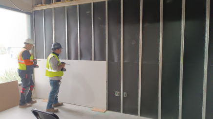
Decoupling is the second lever and the most powerful one, because it attacks the flanking path directly. A wall leaks not only through its face but through its frame: vibration couples into a stud and re-radiates on the far side, short-circuiting all that carefully bought mass. The studio world breaks that path several ways, in ascending order of effectiveness and cost. Resilient channel is a springy hat-shaped metal strip that hangs the drywall off the studs on a flexible mount; it is cheap and, when installed correctly (and it is famously easy to install incorrectly, short-circuited by a single overlong screw), it adds real isolation. Sound isolation clips — rubber-isolated brackets carrying a steel hat-channel — do the same job better and more forgivingly, and are the current studio default. Double-stud and staggered-stud walls go further by giving the two faces of the wall entirely separate framing, so there is no rigid path between them at all: a staggered-stud wall shares a single top and bottom plate but alternates the studs, while a true double-stud wall builds two independent walls with an air gap, the gold standard short of a fully floating room. Each step up the ladder trades cost and wall thickness for decibels, and the returns are real: a decoupled double-stud wall with insulated cavities can reach the high STC 50s to low 60s, comfortably past the SCIF’s Sound Group 4.
Damping is the third lever, and it is where constrained-layer damping compounds — a viscoelastic layer sandwiched between two rigid panels that converts flexural vibration into a trickle of heat. The ubiquitous product is Green Glue, a damping compound troweled or caulked between two layers of drywall; the manufacturer’s own comparative data credits a Green Glue sandwich with roughly the transmission-loss benefit of adding a couple of extra drywall layers, at a fraction of the mass. Damping is most valuable exactly where mass law is weakest — around the low-frequency resonance and coincidence dips — which is why the studio recipe of two layers of drywall with Green Glue between them is so popular: it adds mass and damping in the same operation.
Sealing is the fourth lever and the one the SCIF volumes hammered relentlessly, because it is the one hobbyists skip and then blame the wall. Sound, like water, exploits the smallest continuous path: an unsealed outlet box, a gap under the door, an untreated duct, a back-to-back pair of electrical boxes in the same stud cavity. A wall rated STC 55 in the lab performs like its worst hole once installed, and the worst hole is almost always an airborne leak, not a deficiency of mass. Acoustic sealant at every perimeter, gasketed and drop-seal doors, offset outlet boxes, and baffled or ducted ventilation are not finishing touches; they are the difference between the rated wall and the installed one. The flanking-path and airtight lessons of Volumes 6 and 7 are the same lessons the studio builder learns the hard way, and they transfer without modification.
One caution the studio world teaches and the STC number hides: STC is a speech-band metric and does not measure below 125 Hz. A wall rated to contain a conversation may be transparent to a kick drum or a subwoofer, which is why studios chasing low-frequency isolation build floated rooms and worry about mass and decoupling far beyond what STC credits. For a “quiet lab” whose threat is speech privacy and HVAC rumble, STC is a fair guide; for anything with serious bass, it flatters the wall.
11.5 RF shielding for the hobbyist
The RF problem is the more glamorous one and the one where hobby budgets most need honest expectation management. Volume 8 laid out the physics — shielding effectiveness as the sum of reflection, absorption, and multiple-reflection terms, skin depth shrinking with frequency, and the governing truth that a shielded enclosure is only as good as its worst seam or aperture. All of that applies unchanged at hobby scale; what changes is the achievable number. A professional welded-steel or modular-panel shielded room delivers 80 to 100+ dB of attenuation across a broad band and holds it because every seam is a continuous conductive bond and every penetration is a filter or a waveguide-below-cutoff. A hobbyist working in foil, fabric, mesh, and paint should expect dozens of dB, not a hundred — enough to knock a cellphone off the network, kill the Wi-Fi, and drop a bench measurement’s ambient floor by orders of magnitude, but not enough to defeat a determined receiver at close range. That is not a failure; for the legitimate uses above, 30 to 60 dB is transformative. It is simply not the movie vault.
The material menu, from most to least effective, runs roughly as follows.
Solid metal sheet — copper, aluminum, or steel — is the ideal shield: continuous, thick relative to the skin depth across the whole band of interest, and limited in practice only by its seams. A room lined in overlapped, soldered or bonded copper or aluminum sheet is the closest a hobbyist gets to the professional article, and also the most expensive and laborious. Aluminum flashing and copper sheet from a roofing supplier are the budget path; the labor is in making every seam continuous, because an unbonded overlap is a slot antenna, not a shield.
Conductive fabric and fine mesh are the hobbyist’s workhorses, and the reason the amateur Faraday-room world exists at all. Nickel/copper-plated ripstop and taffeta fabrics — the LessEMF and Mission Darkness (TitanRF) families are the widely used examples — are flexible, staplable, tapeable metallized textiles that deliver genuinely useful broadband attenuation. Vendor figures for a good nickel-copper fabric run on the order of 60 to 80 dB across roughly 10 kHz to tens of GHz (LessEMF’s nickel-copper ripstop is specified around an 80 dB average; its transparent copper mesh for windows is rated nearer 40 dB), for something on the order of fifteen dollars a linear foot at 42-plus inches wide. These numbers are for the material, measured in a fixture; the installed room will do considerably worse wherever seams and the door are imperfect, which is the whole game. Copper or bronze window screen, overlapped and soldered, is the classic ham-radio screen-room material and behaves similarly — excellent conductivity, but every joint must be bonded.
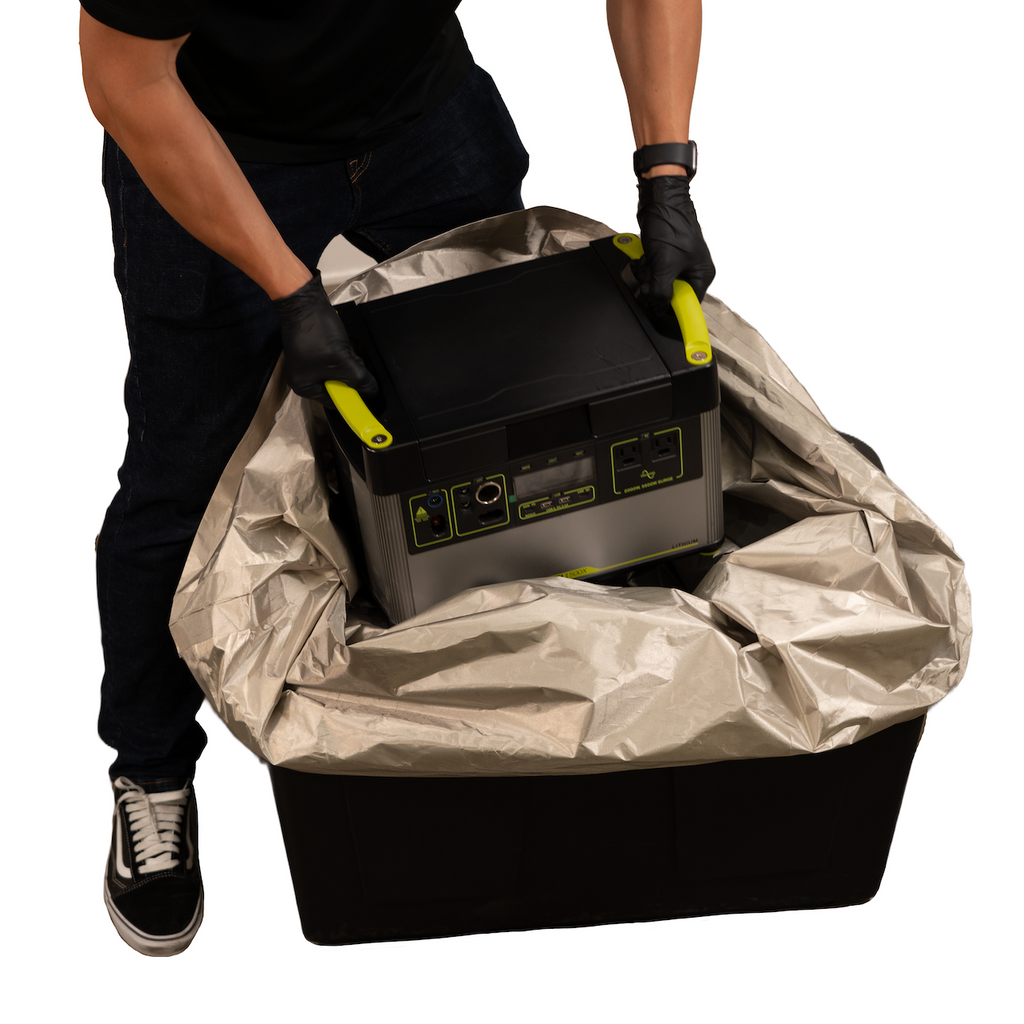
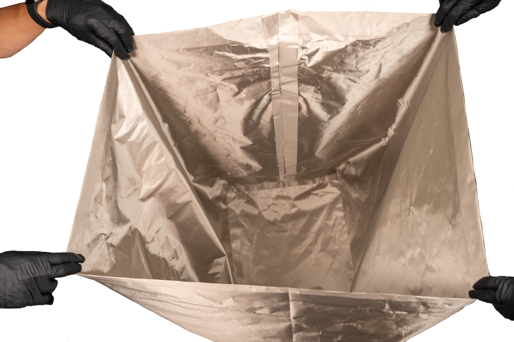
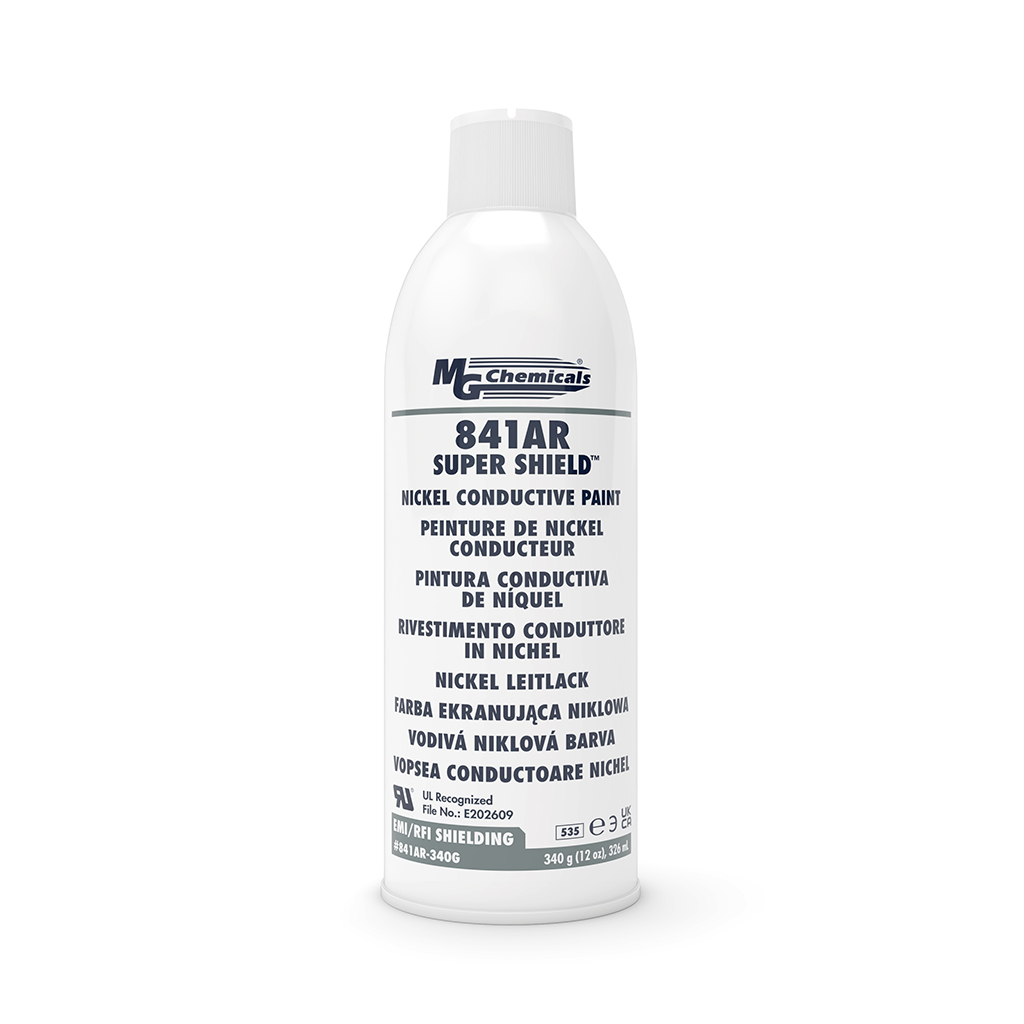
Conductive shielding paint is the material most oversold to hobbyists and most in need of a caveat. Nickel- and graphite-loaded paints — MG Chemicals’ 841 Super Shield nickel coating is the reference product — turn drywall into a conductive surface, and their published shielding effectiveness is real but modest: MG’s own data sheet cites a median attenuation on the order of 50 dB (with a wide ±25 dB spread) per 1.5-mil coat, tested per IEEE-299, over roughly 10 MHz to 18 GHz. That headline number is seductive and misleading for two reasons. First, the paint’s conductivity is far worse than metal’s — surface resistivity around 0.6 ohms per square per coat, versus milliohms for foil — so its shielding is dominated by absorption in a thin, resistive film and falls off badly at lower frequencies where absorption is weakest. Second, and decisively, a painted room is only shielded if every panel is electrically bonded to its neighbors and to the door frame. Paint on drywall with un-bonded seams and an ordinary door is a collection of isolated conductive patches, not an enclosure. Used correctly — every seam bridged with copper tape, a grounded perimeter bus, a gasketed conductive door — nickel paint is a legitimate contributor to a modest shield; used as sold (“paint your walls, block the RF”), it disappoints. It is best thought of as one layer in a system, not the system.
Copper tape is the connective tissue of any of these approaches. Conductive-adhesive copper foil tape bridges the overlaps between foil sheets, fabric panels, and paint runs, turning discontinuous conductors into a continuous envelope. Cheap non-conductive-adhesive tape is a trap — it holds the copper down mechanically but insulates it electrically at the very joint it is meant to bond — so the specification “conductive adhesive” is not optional. Every seam is a soldered or conductive-taped lap joint, or it is an aperture.
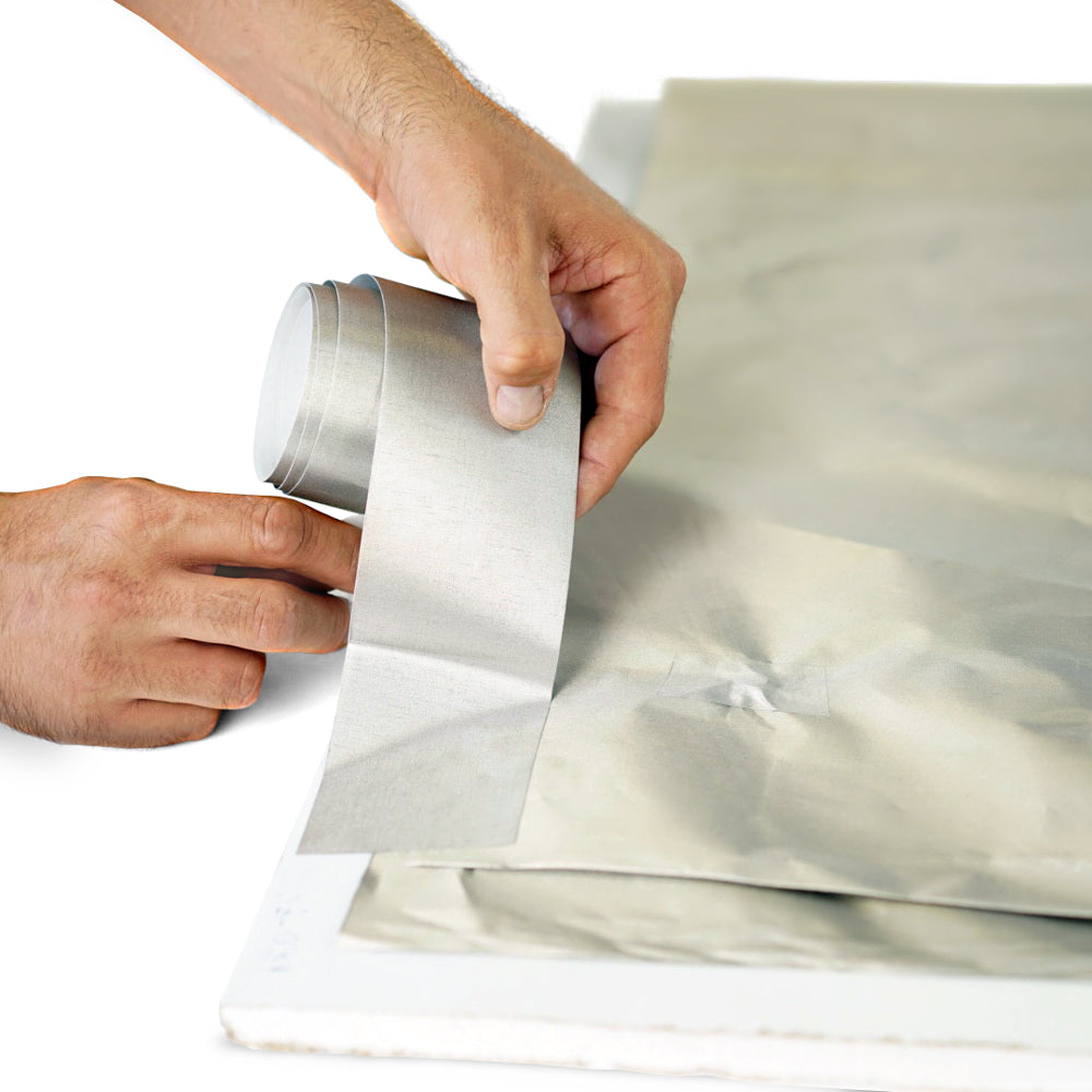
The door and its gasketing are, as at government scale, where most hobby shields fail. A conductive envelope with a poorly-closed door is a room with a permanent aperture the size of the door gap. The professional answer is beryllium-copper fingerstock or a knife-edge gasket making continuous contact around the whole frame; the hobby answer is conductive-fabric gaskets, copper-mesh gasketing, or fingerstock strip bought by the foot, compressed by a latch that pulls the door tight against a clean conductive frame. Whatever the mechanism, the requirement is the same: continuous metal-to-metal (or metal-to-mesh) contact around the entire perimeter of the opening, every time it closes. A door that makes contact on three sides and gaps on the fourth is contributing a slot, and the slot sets the ceiling on the whole room’s shielding effectiveness regardless of how good the walls are.
Apertures and ventilation obey the wavelength rule from Volume 8: a slot leaks efficiently once its longest dimension approaches a half-wavelength, and it leaks measurably long before that. At 2.4 GHz a half-wavelength is about 6 cm, so a gap of a couple of inches is a wide-open door to Wi-Fi; at millimeter-wave frequencies a few millimeters suffice. This is why a real shielded room ventilates through a honeycomb waveguide-below-cutoff panel — a dense array of small hexagonal tubes, each one a waveguide whose cutoff frequency is far above the band of concern, passing air while attenuating fields by many tens of dB. Commercial honeycomb vent panels exist and work beautifully, but they are not cheap, and the honest hobby answer is often simpler: do not put a hole there at all. A small shielded enclosure for intermittent measurements needs no active ventilation; a room that must breathe can often use a single, generously-oversized honeycomb panel or a long, narrow ducted path lined with conductive mesh, accepting that this is the most expensive square foot of the whole build. The cheapest vent is the one that is not cut.
11.6 Getting power, data, and air across the boundary
The moment a shielded room has to do anything — power a device under test, carry data to a computer, exhaust heat — it needs penetrations, and Volume 9’s entire argument reappears at hobby scale: every conductor that crosses the shield is a potential antenna that carries the inside’s fields out and the outside’s noise in, defeating the enclosure through the one path that was supposed to be controlled. The hobbyist’s penetration plan is a scaled-down version of the government one, and it is short.
Power crosses through a mains EMI filter mounted in the shield wall. A feed-through power-line filter — the same Corcom/Schaffner/Astrodyne-style low-pass filter that lives in every piece of certified equipment — bonds its case continuously to the shield and passes 50/60 Hz while shunting high-frequency energy to the shield before it can ride the mains conductor across the boundary. The filter body is the penetration; the conductor never crosses the shield unfiltered. Hobby-grade filtered IEC inlets and panel-mount power filters cost tens of dollars and are the single most important penetration to get right, because the mains cable is the longest, best-coupled antenna in the whole system.
Data should cross on fiber. This is the one place the hobbyist gets a clean win essentially for free: an optical fiber is a dielectric, carries no current, couples to no field, and crosses a shield wall through a small hole (below cutoff at optical-relevant frequencies by an enormous margin) without any filtering at all. A media converter on each side turns Ethernet into light and back, and the shield stays continuous. Any copper data cable, by contrast, is another antenna that must be filtered or avoided — and avoiding it is so much easier that fiber is the default for any serious shielded bench. Volume 9’s fiber-versus-copper argument is, at hobby scale, simply “use fiber.”
Air, if it is needed at all, crosses through the honeycomb panel described above, or not at all. Grounding follows the single-point rule: the shield is bonded to a single, well-defined ground reference, not to a dozen incidental earth paths that would turn the shield itself into a network of ground loops radiating the very noise it was built to exclude. A single heavy bond from the shield to the building’s grounding electrode, with the filter and the fiber-penetration hardware referenced to the same point, is the whole grounding plan for most hobby rooms. The minimal penetration plan, in one sentence: one filtered mains inlet, one fiber pass-through, one honeycomb vent if unavoidable, one ground bond — and nothing else crosses the shield.
11.7 Measuring what you actually built
The defining discipline of the amateur shielded room — the thing that separates a real shield from a hopeful one — is measurement, because shielding effectiveness is invisible and intuition is worthless. A room that “feels” shielded and a room that delivers 50 dB are indistinguishable to the eye, and the seams that ruin a shield are exactly the ones that look fine. The hobbyist verifies, and the tools have become astonishingly cheap.
The poor-man’s IEEE-299 mirrors the professional method: place a known source on one side of the boundary and a receiver on the other, measure the received level, then measure it again with the shield closed, and the difference in dB is the shielding effectiveness at that frequency and geometry. The professional version uses calibrated antennas, a swept signal generator, and a rigorous fixture; the hobby version uses whatever is on the bench, and is perfectly adequate for finding leaks and tracking improvement even if its absolute numbers are not traceable.
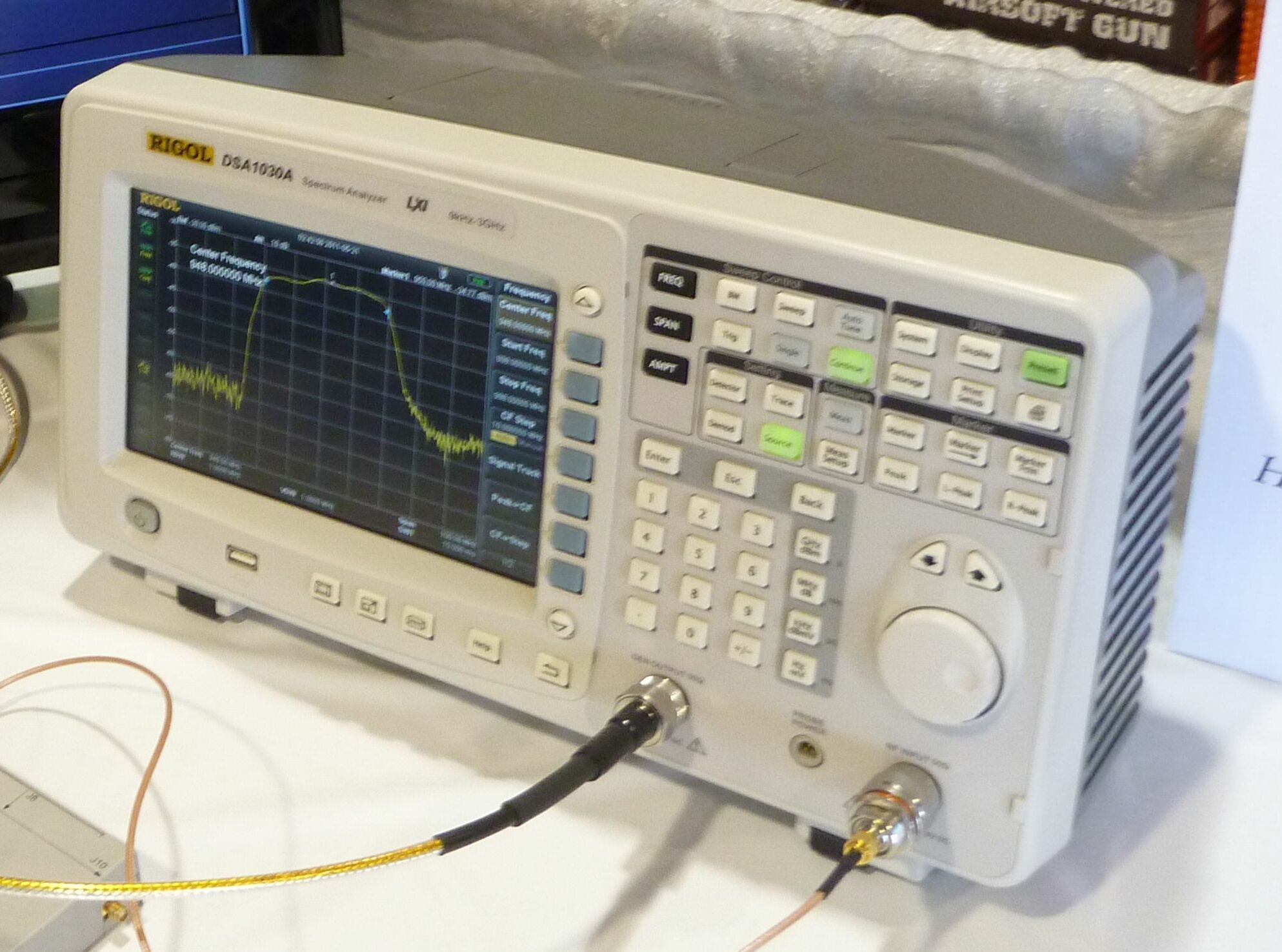
The instruments span every budget. At the low end, a cellphone is a free wideband test source and detector: put a phone inside, close the room, and try to call it — a shield that drops it off the cellular and Wi-Fi networks entirely is doing tens of dB across the bands that matter most for privacy. A key fob, a Wi-Fi access point, or a Bluetooth beacon placed inside gives a repeatable source at a known frequency; watching it disappear (or not) as the door closes localizes leaks fast. One step up, an RTL-SDR dongle (on the order of thirty dollars) with free spectrum software turns a laptop into a broadband receiver that can watch a signal’s level fall as the shield closes — crude in absolute terms, superb for relative before/after comparison. A spectrum analyzer — once a five-figure instrument, now available in benchtop form for a few hundred dollars — does the same job with real calibration and a proper noise floor, and paired with a tracking generator or a signal generator implements the poor-man’s IEEE-299 directly: source outside, analyzer inside, read the attenuation off the screen. And a NanoVNA — a fifty-dollar vector network analyzer that would have been a laboratory centerpiece a generation ago — measures the transmission (S21) between two small antennas placed across the boundary, giving a swept shielding-effectiveness curve that reveals exactly which frequencies leak.

For acoustic verification the equivalent is a calibrated measurement microphone (again, now cheap) and a pink-noise source or even a phone app: play a known level inside, measure the level outside, and the drop approximates the wall’s field transmission loss. It will not be a laboratory STC — that requires a two-room reverberant suite — but it finds flanking leaks and confirms that the installed wall bears some resemblance to the rated one, which is the whole point. The expectation to manage, in both domains, is that the installed number is always worse than the material’s datasheet, and the gap between them is the sum of every seam, gap, and penetration the builder did not perfect. Measurement is how that gap gets found and closed, one leak at a time.
11.8 A buildable spec: the spare-bedroom quiet lab
To make the trade-offs concrete, consider a worked example: converting a spare bedroom — call it roughly ten by twelve feet — into a “quiet lab” that is both meaningfully sound-isolated and RF-shielded to hobby standards. The costs below are ballpark material figures for illustration, not a quote; regional prices and the inevitable second trip to the hardware store will move them, and labor is assumed to be the builder’s own weekends.
The acoustic layer starts from the studio recipe. The existing wall gets a decoupled second leaf: sound-isolation clips and hat channel on the existing studs (or, on a bigger budget, a fully independent double-stud wall built inboard), the cavity filled with ordinary mineral-wool batts, then two layers of 5/8-inch drywall with Green Glue between them and a layer of mass-loaded vinyl in the assembly for compact mass. Every perimeter — floor, ceiling, corners, and especially the door — is sealed with acoustic sealant, and the hollow-core bedroom door is replaced with a solid-core door on full gasketing with a drop seal at the threshold. That stack — decoupling plus mass plus damping plus sealing — lands a wall in the STC 50s, past the SCIF’s Sound Group 3 and into Sound Group 4 territory, for a few hundred dollars of drywall, Green Glue, MLV, and clips per wall.
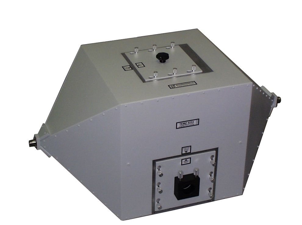
The RF layer is built inside the acoustic layer, because the conductive envelope wants to be continuous and the last surface before the finish is the place to make it so. The budget tier lines the six surfaces — walls, ceiling, and floor, because a shield with an unshielded floor is a five-sided box — in overlapped nickel-copper shielding fabric or aluminum foil, every seam bridged with conductive copper tape, brought around to a gasketed conductive door (a metal door or a fabric-wrapped one, sealed with fingerstock or conductive-fabric gasket against a bonded frame). Power enters through a panel-mount mains EMI filter; data crosses on fiber through a small pass-through; ventilation, if the room needs it, is a single honeycomb waveguide vent or is omitted in favor of intermittent use with the door open between measurements; and the whole envelope is bonded to a single ground point. Realistically this budget tier — fabric or foil, tape, a gasketed door, a filter, fiber, single-point ground — delivers somewhere in the 30 to 60 dB range across the common bands, wildly variable with the quality of the door seal, and is transformative for privacy and bench-noise purposes while being nowhere near a certified room.
The tiers stack predictably. A budget build (fabric or foil lining, conductive tape, a carefully gasketed ordinary door, a filtered inlet, fiber) is a few hundred to a couple of thousand dollars in materials and buys dozens of dB. A mid build (soldered copper mesh or bonded aluminum sheet on all six surfaces, a purpose-built fingerstock-gasketed shielded door, commercial honeycomb vents, a proper feed-through filter panel) climbs into the several-thousand-dollar range and buys a more repeatable 60-to-80-ish dB with a real door. A serious build is where the hobbyist meets the professional and the honest advice is stop building and buy — a commercial modular RF-shielded room (the Select Fabricators / ETS-Lindgren / Ramsey class of panel enclosures) delivers a warranted 80-to-100+ dB with a certified door and vents, and no amount of copper tape and weekend labor reliably matches a factory-bonded panel seam. The cost curve is steeply diminishing: the first 40 dB is cheap, the next 20 dB is expensive, and the last 20 dB is why professional shielded rooms cost what they cost. A hobbyist should decide honestly which decibel they actually need and stop there, because every dB past the requirement is money spent making a room heavier for no benefit — the same lesson Volume 8 drew about the CTTA pulling the shielding lever exactly as far as the threat demands and no farther.
11.9 What cannot be replicated, and staying on the right side of the line
Several things on the government side of this deep dive have no hobby equivalent, and pretending otherwise is the failure mode to avoid. Full TEMPEST certification is unreachable: the emanation limits are classified, the test regime is government-controlled, and a CTTA’s countermeasures determination is a credentialed judgment, not a measurement a hobbyist can make — a person can characterize their own device’s emanations as a research exercise, but they cannot certify a room to a standard whose numbers are secret. The accredited alarm and monitoring regime — the IDS/ACS, the central-station monitoring contract, the response force, the SSM’s inspection cycle from Volume 10 — is an operational and contractual apparatus, not a product; a hobbyist can install a perfectly good alarm, but it is a home alarm, not an accredited intrusion-detection system tied to a cleared monitoring station. And government reciprocity — the property that one agency’s accreditation is honored by another — is meaningless outside the accreditation system entirely; there is nothing for a private room to be reciprocal to.
The legal line is bright and worth stating without hedging. A private citizen may build any shielded or isolated room they like, on their own property, for any of the legitimate purposes above; none of that requires permission and none of it is exotic. What a citizen may not do is claim to operate a SCIF, represent a private room as accredited, or — the one that actually carries criminal exposure — possess or handle classified material, which no construction project can authorize because the authorization is a clearance-and-contract relationship a private individual simply does not have. The correct mental model is that the hobby build is a shielded lab, described honestly as such, used for one’s own lawful measurements and privacy. Everything in this volume is in service of building that room well; none of it is in service of pretending it is something it legally cannot be.
11.10 The same physics, minus the paperwork empire
The quiet punchline of the whole deep dive is that the hobbyist’s shielded lab and the government’s accredited SCIF are, at the level of physics, the same room. Mass law does not know whether an Accrediting Official signed the drawings. Skin depth is indifferent to the Fixed Facility Checklist. A slot antenna leaks the same 2.4 GHz whether the wall around it cost a hobbyist four hundred dollars or a contractor four hundred thousand. Every principle these eleven volumes developed — the continuous true-floor-to-true-ceiling perimeter, the asymmetric mass stack for speech containment, the decoupled leaf that defeats the flanking path, the conductive envelope whose worst seam sets its ceiling, the honeycomb vent and the feed-through filter and the fiber pass-through that let a sealed box still function, the relentless discipline of sealing and measuring every hole — is available to the private builder at hobby scale and hobby cost. The difference between the two rooms is not the engineering. It is the accreditation: the sponsor, the AO, the cleared labor, the inspectable-space determination, the monitoring contract, and the mountain of paper that turns a very good shielded room into a facility with a legal status. The engineering is the part a person can own. The paperwork empire is the part they cannot — and, for a spare-bedroom lab whose only mission is honest measurement and a little privacy, the part they do not need.
Sources
- LessEMF, product data for nickel-copper ripstop shielding fabric (≈80 dB average, 10 kHz–40 GHz), RadioScreen copper mesh (≈40 dB), copper taffeta, and silver-content fabrics, with per-linear-foot pricing. https://lessemf.com/product/ni-cu-ripstop-fabric/ ; https://lessemf.com/product/radioscreen-mesh/ ; https://www.lessemf.com/fabric4.html
- MOS Equipment / Mission Darkness, “TitanRF Faraday Fabric FAQ & D.I.Y. Shielded Enclosures” — metallized (nickel/copper) Faraday fabric, seam-bonding with conductive tape, and hobby enclosure construction. https://mosequipment.com/pages/titanrf-faraday-fabric-faq
- MG Chemicals, Super Shield 841 Nickel Conductive Coating technical data sheet — median attenuation ≈50 dB ±25 dB per 38 µm (1.5 mil) coat, 10 MHz–18 GHz, tested per IEEE Std 299-1997; surface resistivity ≈0.6 Ω/sq per coat. https://mgchemicals.com/downloads/tds/tds-841-l.pdf ; product page https://mgchemicals.com/products/conductive-paint/conductive-spray-paint/shielding-paint/
- Second Skin Audio, “Green Glue vs Mass Loaded Vinyl” — function of damping vs. added mass, and MLV’s ≈7–10 STC-point contribution. https://www.secondskinaudio.com/soundproofing/green-glue-vs-mass-loaded-vinyl/
- Green Glue / Soundproofing Company comparative transmission-loss data (constrained-layer damping equivalent to added drywall layers) and studio wall recipes. https://www.tmsoundproofing.com/Green-Glue-Data-and-Comparison.html ; https://www.soundproofingcompany.com/soundproofing-articles/in-the-studio-recording-magazine
- Commercial Acoustics, “Mass Loaded Vinyl Sound Barrier: STC Ratings & Cost Guide,” and Acoustical Solutions, “How to Achieve STC 50 or Higher in Wall and Ceiling Assemblies” — decoupling (resilient channel, isolation clips, double/staggered stud), mass, and the STC-below-125 Hz caveat. https://commercial-acoustics.com/guides/mass-loaded-vinyl-sound-barrier-uses/ ; https://acousticalsolutions.com/stc-rating-50
- On amateur Faraday-cage / shielded-room construction, seam bonding, grounding, and cellphone/spectrum-analyzer verification: Engineer Fix, “How to Build a Faraday Cage Room for EMF Shielding,” https://engineerfix.com/how-to-build-a-faraday-cage-room-for-emf-shielding/ ; Hamshack Reviews, “Faraday Cage for RF Shielding,” https://hamshackreviews.com/faraday-cage/
- Henry W. Ott, Electromagnetic Compatibility Engineering (Wiley, 2009) — shielding effectiveness (SE = R + A + B), aperture/slot leakage vs. wavelength, and feed-through power-line filtering (the engineering underlying the material choices and penetration plan here).
- IEEE Std 299, Standard Method for Measuring the Effectiveness of Electromagnetic Shielding Enclosures — the professional SE test method the hobbyist “poor-man’s” source/receiver measurement mirrors. https://standards.ieee.org/ieee/299/1728/
- On honeycomb waveguide-below-cutoff air vents and feed-through EMI/power filters at the shield boundary: MAJR Products honeycomb waveguide panels, https://www.majr.com/product/honeycomb-waveguide-panels/ ; ETS-Lindgren shielded waveguide air vents, https://www.ets-lindgren.com/product/emi-rfi-shielded-waveguide-air-vents/ ; Astrodyne TDI EMI/power-line filters, https://store.astrodynetdi.com/emi-filters/tempest.html
- On commercial modular RF-shielded rooms (the “serious tier — buy, don’t build” option delivering warranted 80–100+ dB): Select Fabricators RF-shielded products, https://www.select-fabricators.com/rf-shielded-products/ ; Raymond EMC shielded enclosures, https://raymondemc.com/products/shielded-doors/
- On low-cost measurement instruments (NanoVNA vector network analyzer, RTL-SDR, benchtop spectrum analyzers) for hobby SE and RF measurement — general amateur-radio and SDR community documentation; NanoVNA project resources. https://nanovna.com/
- ODNI / NCSC, IC Tech Spec for ICD/ICS 705 v1.5.1 — the Sound Group/STC targets and construction principles the hobbyist build is measured against (public release). https://www.dni.gov/files/NCSC/documents/Regulations/IC_Technical_Specifications_for_Construction_and_Management_of_Sensitive_Compartmented_Information_Facilities_v151_PDF.pdf
Comments (0)