Scif · Volume 8
RF and TEMPEST: Shielding Against Emanations
8.1 The signal that leaves without permission
Every previous volume has treated the SCIF as a container for deliberate signals: the conversations held inside it, the documents read there, the classified video pulled to the table. This volume is about the signals nobody intends to send. A running computer, a display, a keyboard, a crypto device, a length of red cabling — each is, whether its designer wished it or not, a small and inadvertent radio transmitter. It radiates. It conducts. It couples onto every wire that leaves it and onto the mains that feeds it, and buried in that radiation and conduction is a faithful, if attenuated, copy of what the equipment is actually doing. The discipline of preventing an adversary from recovering information from those unintended signals is emanation security; the U.S. program and family of standards that governs it carries the cover name TEMPEST; and the physics underneath it is the most purely electrical-engineering subject in the entire series. This is the volume where the SCIF stops being a bureaucratic object and becomes a Faraday cage with a mortgage.
The threat is not speculative and it is not new. Volume 2 told the founding story: in 1943 a Bell Telephone Laboratories engineer noticed that a 131-B2 mixer — part of the Army’s one-time-tape teletype system — threw a spike onto an oscilloscope at the far end of the lab every time it enciphered a character. The electromechanical guts of the machine were radiating the plaintext into the room and down the signal line, after all the mathematical trouble of the one-time tape had been taken to make the ciphertext unbreakable. Bell proved the point by parking a technician across the street and recovering a useful fraction of a test message from the emanations alone. The wartime fix was a controlled zone; the phenomenon was named compromising emanations; and the effort to characterize and suppress it became TEMPEST. That is the callback. This volume picks up where it left off: with the modern threat model and the engineering that answers it.
The single event that dragged compromising emanations out of the classified world and into the open literature was Wim van Eck’s 1985 paper in Computers & Security, “Electromagnetic Radiation from Video Display Units: An Eavesdropping Risk?” Van Eck, a Dutch engineer, showed that the raster of a cathode-ray-tube monitor — the electron beam sweeping line by line, its intensity modulated by the video signal — radiates a broadband signal whose horizontal and vertical structure mirror the screen’s. With a modified television receiver and a means of re-synchronizing to the monitor’s line and frame rates, he reconstructed the contents of a display at a distance, through walls, using equipment a hobbyist could assemble. The demonstration was deliberately public and deliberately alarming: the governments that had classified this problem for forty years suddenly had to reckon with a civilian who had rediscovered it with a soldering iron and a scope. “Van Eck phreaking” entered the vocabulary, and the general concept — that a screen leaks its contents electromagnetically — has been openly citable ever since.
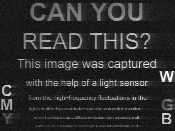
The most rigorous open work on the subject came out of the University of Cambridge, chiefly from Markus Kuhn, whose late-1990s and 2000s research on “compromising emanations” is the canonical academic treatment. Kuhn (with Ross Anderson) coined Soft Tempest — the observation that because the emanation from a digital display depends on the content being displayed, software can deliberately shape it: hide a low-bandwidth covert channel in what looks like ordinary screen text, or, defensively, filter fonts and dither pixels so the radiated signal carries far less recoverable information. He extended the threat past the CRT to flat-panel displays and their digital interface cables, showed that keyboards and other peripherals emit exploitable signals, and — most vividly for an engineer — demonstrated optical compromising emanations: the little activity LED on a modem or router can be modulated by the serial data it indicates, and the flicker of a CRT’s light output, even bounced diffusely off a wall, can be captured with a photosensor and deconvolved back into readable text.

Two things must be said plainly, and then held to for the rest of the volume. First, the concept is thoroughly public: equipment emanates, the emanation carries information, and an adversary at some standoff distance can try to recover it. Van Eck, Kuhn, and the NSA’s own declassified 1972 monograph TEMPEST: A Signal Problem (released with redactions in 2007) put the concept firmly in the open record. Second, the numbers are not public. The specific emanation limits an equipment must meet, the frequency-by-frequency test envelopes, and the zoning distances that relate an equipment’s residual leakage to how close an adversary might get all live in the NSTISSAM/CNSSAM TEMPEST family — chiefly NSTISSAM TEMPEST/1-92 and its lineage back through NACSIM 5100 — and they are classified. This volume describes the physics and the construction in the openly published units of the trade: shielding effectiveness in decibels, skin depth in millimetres, aperture dimensions in wavelengths. It does not invent a single classified limit, and the reader should distrust any hobbyist source that claims to quote one.
8.2 The countermeasure hierarchy, and who decides
Emanation security is not solved by any one measure but by a hierarchy of them, applied in whatever combination a given facility’s threat warrants. It is worth laying the hierarchy out before diving into the Faraday physics, because the physics is only the last and most expensive layer.
The first and cheapest countermeasure is control of space — the modern descendant of the wartime control zone. If the emanation from a piece of equipment falls below what an adversary could exploit before that adversary reaches the nearest point they could physically occupy, the emanation is, operationally, not compromising. Enlarge the controlled area around the equipment and you relax everything else. This is the concept of an inspectable space or controlled space, and it is the reason a SCIF in the middle of a large, fenced, patrolled government campus faces a fundamentally different emanation problem from an identical room sharing a wall with a leased office or a public street. The distances that make this concrete are classified; the principle is not, and it is the lever that determines whether a facility needs shielding at all.
The second layer is equipment. Rather than shielding a whole room, one can use equipment that has itself been engineered and tested to emanate little — the certified-equipment approach. The government maintains a program of TEMPEST-certified products (historically catalogued so that an accreditor could specify equipment already tested against the classified limits), and a specialty industry builds and sells such gear. Certified equipment is expensive and lags the commercial state of the art, so it is used where it must be and avoided where control of space or facility shielding can carry the load instead. The engineering point is that the box and the room are substitutes at the margin: money spent hardening equipment is money not spent on copper, and vice versa.
The third layer — the subject of the rest of this volume — is the shielded facility: enclosing the whole volume in a conductive envelope so that whatever the equipment inside emanates is attenuated at the boundary before it can escape, and whatever an adversary might beam in is attenuated on the way through. This is the Faraday cage as a building system, and it is the most thorough and by far the most costly answer.
Who chooses among these layers is a question Volume 3 already answered, and the answer is worth restating because it is frequently gotten wrong. The Authorizing Official owns the TEMPEST decision for a facility. The technical judgment behind it is rendered by a Certified TEMPEST Technical Authority — the CTTA — who evaluates the facility’s location, its inspectable space, the sensitivity of what will be processed, and the threat, and determines what emanation countermeasures (if any) are required. A SCIF is not shielded because SCIFs are shielded; it is shielded if, and only to the degree that, the CTTA’s countermeasures determination says it must be. Hold that thought — it is the corrective to the most common misconception about these rooms, and this volume returns to it at the end.
8.3 The Faraday cage an engineer will actually reason about
Strip away the classification and the shielded room is a boundary-value problem an EE met as an undergraduate. A time-varying electromagnetic field is incident on a conducting sheet. Some of it reflects at the front surface because of the impedance mismatch between free space and the metal; some of what gets in is absorbed as it propagates through the lossy conductor and is dissipated as heat; and a correction accounts for the wave that bounces between the two faces of a thin sheet. The standard bookkeeping, due originally to Schelkunoff and taught in every EMC text (Ott’s Electromagnetic Compatibility Engineering is the usual reference), writes the total shielding effectiveness as a sum in decibels:
SE = R + A + B
where R is reflection loss, A is absorption loss, and B is a multiple-reflection correction that matters only when the shield is thin compared with a skin depth (in which case B is negative — the internal re-reflections reduce the effectiveness). Each term is a number of decibels; a shield rated at, say, 100 dB attenuates the field by a factor of 100,000 in amplitude. The virtue of the decibel formulation is that these mechanisms simply add, so an engineer can reason about them one at a time.
Reflection loss dominates at low frequencies and for good conductors, and it is larger for the electric field than for the magnetic. The physical reason is impedance mismatch: free space presents a wave impedance of 377 ohms, a copper sheet presents milliohms, and the enormous ratio means most of an incident electric field simply bounces off. Magnetic fields are the hard case — a low-frequency magnetic field sees a much smaller mismatch and is reflected far less, which is why magnetic shielding at low frequencies is a genuinely different and harder problem than electric-field shielding, and why it often calls for high-permeability materials (mu-metal) rather than high-conductivity ones.
Absorption loss is the term that saves you at high frequencies, and it is governed by skin depth. In a good conductor a propagating field decays exponentially with depth, the 1/e distance being the skin depth
δ = √(2 / ωμσ)
with ω the angular frequency, μ the permeability, and σ the conductivity. For copper the skin depth is about 2 mm at 1 kHz, 66 µm at 1 MHz, and 2 µm at 1 GHz — it falls as the inverse square root of frequency. The absorption loss through a sheet of thickness t is a tidy 8.69·(t/δ) decibels (that is, one skin depth of thickness buys 8.69 dB, and the loss piles up linearly in thicknesses). The consequence is the single most counter-intuitive fact about shielding for a newcomer and the most obvious one for a microwave engineer: at high frequencies you do not need much metal at all. A few thousandths of an inch of copper is many, many skin depths thick at a gigahertz and provides absorption loss measured in the hundreds of decibels. A SCIF shield is not thick because the metal needs to be thick to stop the wave — a thin foil stops the wave. It is “thick” (structurally robust) because it has to survive construction, carry its own weight, be welded or clamped into continuous joints, and not develop holes over decades of service.
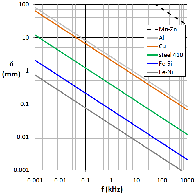
That last sentence in the caption is the hinge of the entire subject, and it deserves its own section.
8.4 Apertures, seams, and the tyranny of the worst hole
An ideal, seamless, hole-free conductive shell of any reasonable thickness provides shielding effectiveness so high — well past 100 dB across the spectrum of interest — that the material is essentially never the limiting factor. Real shields are not seamless. They are built from panels that must be joined, they have a door that must open, they must pass air, power, water, signal, and people, and every one of those necessities is a hole. A shield is only as good as its worst aperture, seam, or gasket. This is not a slogan; it is a quantitative statement, and it is why practicing shielding engineers spend almost none of their time thinking about metal and almost all of it thinking about joints.
The physics of aperture leakage is again textbook. A slot or seam in a conducting sheet radiates like a slot antenna, and its leakage rises with frequency until the slot’s longest dimension approaches a half wavelength, at which point it couples with brutal efficiency. The controlling dimension is the longest linear extent of the opening, not its area — a long thin crack leaks far worse than a round hole of the same area, because it is the length that resonates. A one-centimetre-long seam is electrically short and leaks little at 100 MHz (three metres of wavelength) but becomes a half-wave slot near 15 GHz. This is why a shielded enclosure’s specification is dominated by the treatment of every linear joint: panels are lapped and bolted on close centres, or continuously welded, or clamped over conductive gaskets, all in the service of never letting a seam grow electrically long or an impedance develop across it.
There is one beautiful exception to the “holes are bad” rule, and it is the workhorse of shielded-facility design: the waveguide below cutoff. A hollow conductive tube behaves as a high-pass filter. Below a cutoff frequency set by its cross-section, a wave entering the tube does not propagate — it evanesces, decaying exponentially along the tube’s length. For a round tube the cutoff wavelength is about 1.7 times the diameter; below cutoff the attenuation runs to roughly 30 dB per unit length equal to the diameter (about 32 dB for the dominant mode per diameter of length). The design rule that falls out is that a penetration made as a tube whose length is several times its diameter, operated well below its cutoff frequency, provides very high attenuation while remaining a physical opening. This is how a shielded room breathes and drinks: air passes through a dense pack of small waveguide tubes — a honeycomb — and non-conductive services (like a plastic pipe) pass through a single tube long enough that the below-cutoff attenuation across the operating band matches the wall’s rating. The whole of Volume 9 is, in effect, a catalogue of ways to exploit the waveguide-below-cutoff so that necessary things can cross the shield without punching a resonant hole in it.
8.5 Building the shell
With the physics in hand, the construction choices become legible. There are, broadly, three ways to build the conductive envelope of a shielded facility, and they trade cost, performance, and permanence against one another.
The most common purpose-built shielded room is a modular panel enclosure: prefabricated panels — a conductive skin (galvanized steel is typical; copper for the highest performance) bonded to a rigid core — bolted or clamped together on a frame, with conductive gaskets in every joint. The virtue is that it is a factory-tested, repeatable, demountable product: it can be assembled inside an existing building, disassembled and moved, and its performance is characterized before it ships. The vulnerability is the same as its virtue — it is all seams, so the whole performance lives in the clamping pressure and the gasketing of a great many bolted joints, and it degrades if the joints loosen or corrode.
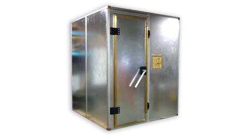
The highest-performance fixed installations are welded steel single-shield rooms: sheet steel continuously seam-welded into a monolithic box, eliminating the bolted joints entirely in favour of welds. A well-executed welded shield can hold very high effectiveness across a broad band and hold it for decades, because there are no clamped seams to relax. It is correspondingly expensive and permanent — it is fabricated in place and it does not move. For facilities demanding the utmost, a double electrically-isolated shield (two nested shells, insulated from each other) buys still more attenuation and controls the grounding problem discussed below, at roughly twice the cost of one shell.
At the other end sits architectural shielding: rather than a discrete room-within-a-room, the shield is built into the building fabric — conductive foil or fine metal mesh laminated into the walls, ceiling, and floor, with the seams overlapped and bonded, the whole thing tied together and treated at every penetration. Architectural shielding is less demonstrably perfect than a welded box (it is harder to inspect a foil buried in a wall than a weld you watched being made) but it disappears into ordinary-looking construction and can shield a large, oddly shaped space that a modular kit could not. Many facilities blend approaches: a modest architectural treatment for the general volume and a hardened modular or welded core for the most sensitive processing, matching the shielding to the CTTA’s determination rather than gold-plating the whole footprint.
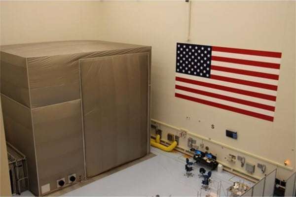
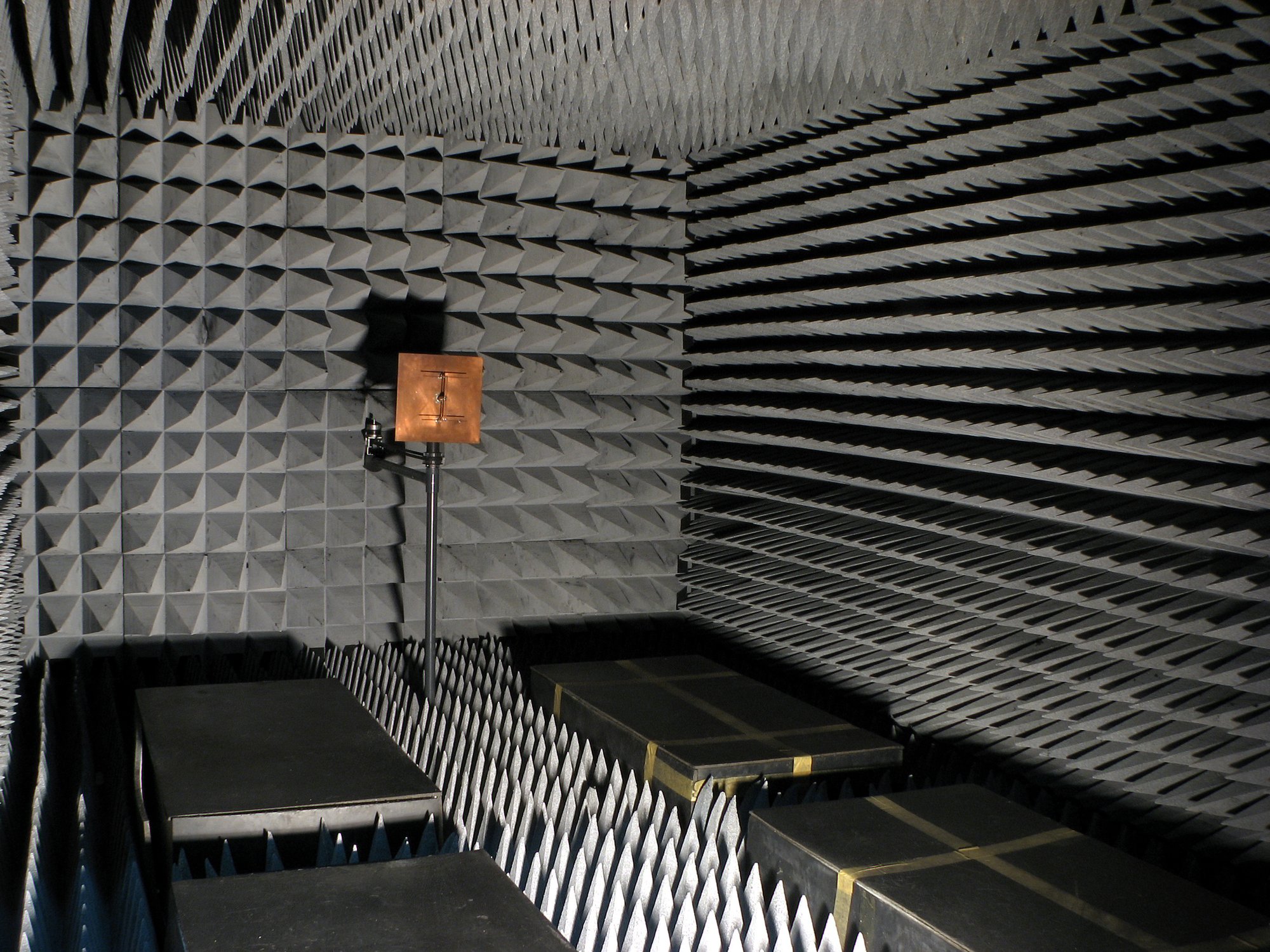
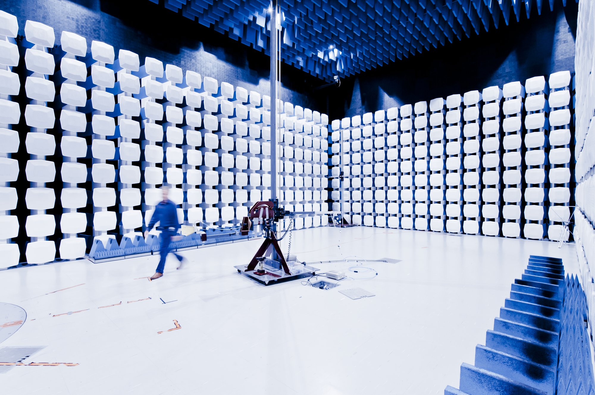
However the shell is built, its performance is not asserted — it is measured, and the measurement has a public standard: IEEE Std 299, Standard Method for Measuring the Effectiveness of Electromagnetic Shielding Enclosures. IEEE-299 defines how to characterize an enclosure’s shielding effectiveness across low frequencies (magnetic-field, small-loop measurements), the resonant mid-band, and the high-frequency plane-wave region, using transmit and receive antennas inside and out and a disciplined survey of the walls, seams, door, and penetrations. It is the yardstick that turns “we built a Faraday cage” into a defensible number, and it is the acceptance test a shielded SCIF shell is signed off against. (IEEE-299 measures the facility’s attenuation; it is a different exercise from testing an equipment against the classified emanation limits, which is a matter for the certified equipment program, not the building inspector.)
8.6 The door is the hard part
Ask anyone who builds shielded rooms what limits their performance and the answer is immediate and unanimous: the door. Every other seam in the shell can be permanently welded or clamped shut. The door cannot — it has to open thousands of times and close to a perfect electrical seal every time, across a gap that must be an RF short circuit when shut and an ordinary doorway when open. It is the one seam that is also a mechanism, and it is where shielded-enclosure engineering earns its money.
The classic solution is the knife-edge and fingerstock door. A hardened knife-edge blade, mounted around the door, closes into a channel lined with rows of springy beryllium-copper fingerstock — hundreds of individually sprung contact fingers that wipe against the blade as the door shuts, establishing a continuous, gas-tight (electrically speaking) contact all the way around the perimeter with no long unclosed seam anywhere. Beryllium copper is chosen for the fingers because it combines high conductivity with excellent spring memory, so the fingers keep their contact force over enormous numbers of cycles. The knife-edge design is superb electrically — it is how the very highest-attenuation doors are built — but it is demanding mechanically: the fingerstock wears, it can be damaged by grit or by a dropped tool, it needs periodic inspection and replacement, and the door needs real force to seat, which is why heavy shielded doors are often mechanically or pneumatically assisted.
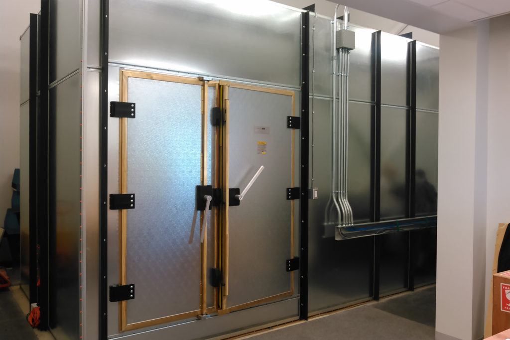
The alternative to a wiping knife-edge is a pneumatic RF gasket: an inflatable conductive gasket that is deflated (so the door swings freely with no contact wear) and then inflated once the door is closed, pressing a conductive surface into continuous contact around the frame. Pneumatic doors trade the fingerstock’s mechanical simplicity for an air system and its maintenance, but they eliminate wiping wear and can seal very large or heavy openings with modest closing force. Whichever approach is used, the door is the component most likely to be the facility’s weakest link over its service life, and it is the first thing a periodic shielding-effectiveness re-test scrutinizes.
8.7 Vents, filters, and the single point where everything enters
A sealed conductive box with a good door would be a fine shield and an uninhabitable one. People need air; equipment needs power and cooling and data. Every one of those services is a conductor or an opening that would ruin the shield if run through it naively, and the art of the shielded facility is passing them through without punching a hole. This is the subject Volume 9 develops in full; here it is enough to name the three canonical treatments, because they complete the picture of the envelope.
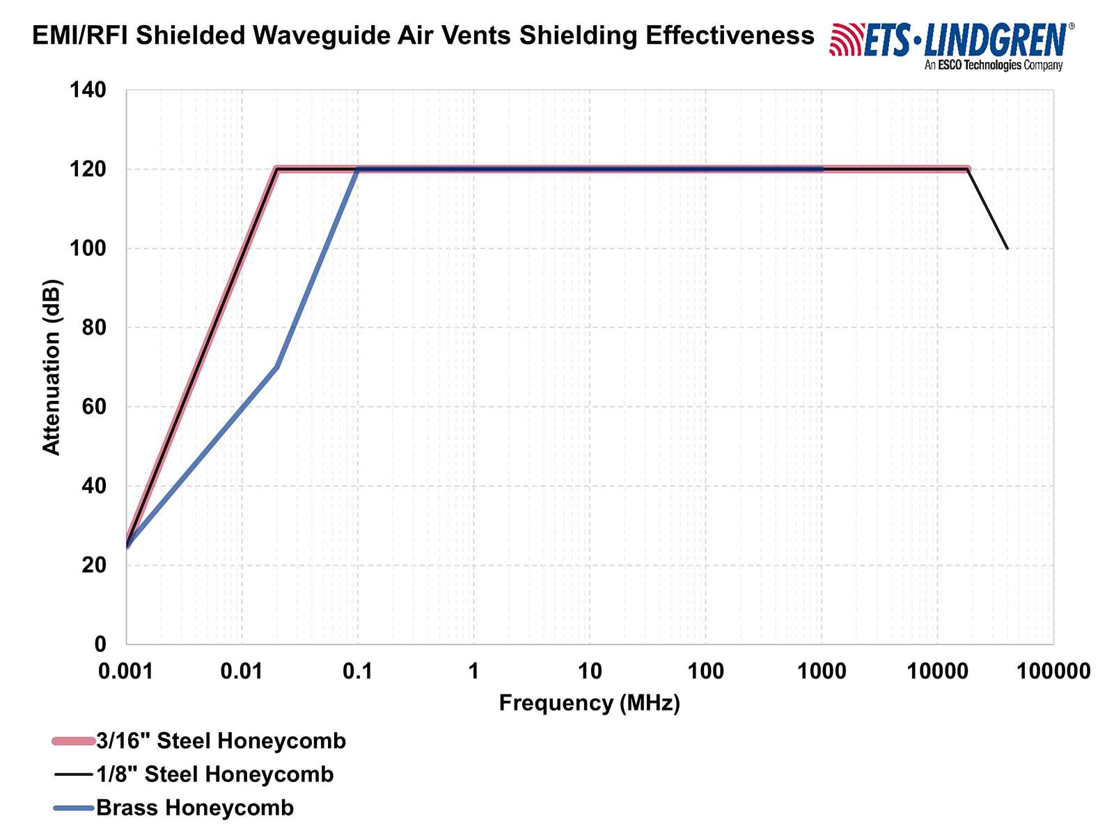
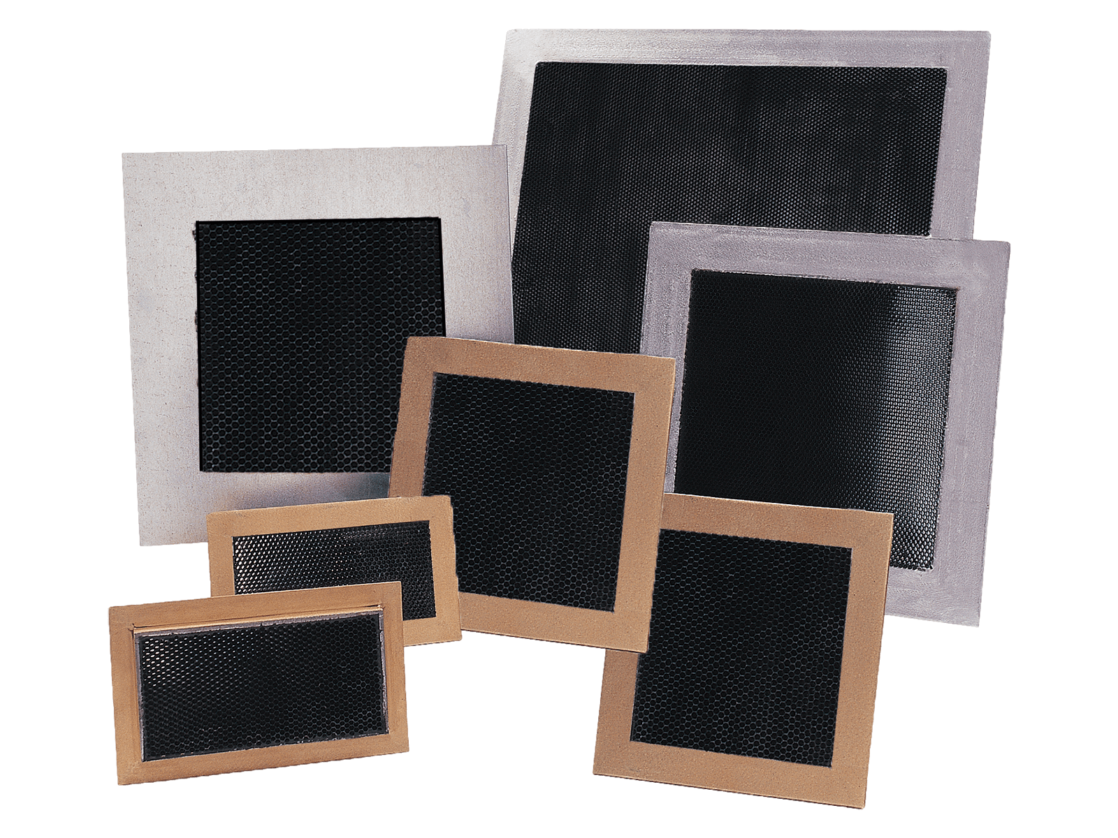
Air passes through honeycomb waveguide vents — the below-cutoff trick made into a product. A vent is a dense honeycomb of small conductive tubes brazed or soldered into a frame; each cell is a waveguide operated far below its cutoff, so the pack passes air with low pressure drop while attenuating RF by the same 100-plus decibels as the wall around it (Figure 4). The honeycomb bonds continuously to the shield at its frame, so it introduces no seam — it is a large opening that is nevertheless not electrically a hole.
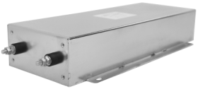
Every conductor that crosses the shield — every power line, and in the classic architecture every metallic signal line — passes through a filter mounted in the shield wall. A power-line RF filter is a low-pass network (series inductors, shunt feed-through capacitors) built into a shielded can that bolts through the wall, so that the 50/60 Hz power passes freely while the RF riding on the line, in either direction, is reflected and attenuated by tens to a hundred-plus decibels. The filter’s case is bonded to the shield and its feed-through construction means the “dirty” and “clean” sides of the line never share an unfiltered path. A filter that is not continuously bonded to the shield, or that lets its input and output wires couple around it, is worse than useless — it provides a false sense of security while the RF simply bypasses it. Filtering every penetrating conductor is not optional garnish; an unfiltered mains lead is an antenna that carries the room’s emanations straight out to the utility transformer.
Both of the above converge on a discipline: services should enter the shield at one place, through a bulkhead penetration panel where all the filters and waveguide entries are grouped and continuously bonded to the shield, rather than being scattered around the perimeter. Concentrating the penetrations makes them inspectable and testable, and it supports the single-point grounding philosophy that shielded facilities live by. Ground is not the innocuous concept a mains electrician treats it as; in a shielded room a ground conductor is one more penetrating wire, and if the shield is bonded to building ground at more than one point, the resulting ground loop can carry currents that couple energy across the very boundary the shield exists to enforce. High-performance installations therefore isolate the shield and reference it to ground at a single, controlled point, so that no loop closes through the structure. The grounding scheme is as much a part of the shield’s performance as the copper is — a fact that surprises people who think of grounding purely as a safety measure.
8.8 RED/BLACK: keeping the plaintext away from the wires that leave
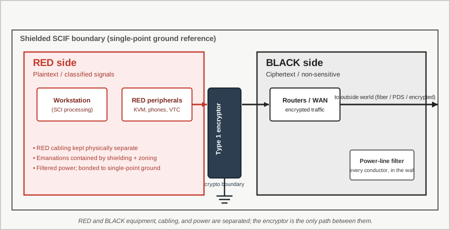
Shielding stops emanations from leaving the room. It does nothing about the possibility that, inside the room, a wire carrying plaintext induces its signal onto a wire that is destined to leave — at which point the classified signal is conducted out past the shield on a perfectly legitimate cable. Preventing that is the province of RED/BLACK separation, a doctrine as old as the 131-B2 and as public in concept as it is classified in its numbers.
The vocabulary is exactly what it sounds like. RED equipment, wiring, and power carry unencrypted classified information — plaintext, in the electrical sense: the signal on the input side of an encryptor, the video driving a classified display, the audio of a classified conversation before it is protected. BLACK equipment and wiring carry either encrypted information or no classified information at all — the output of the encryptor, the general-purpose network, the ordinary building power. The entire object of the discipline is to ensure that RED signals never couple, by radiation or conduction or common impedance, onto BLACK conductors, because a BLACK conductor is allowed to leave the controlled space and a RED one is not. An encryptor is precisely the device that converts a RED signal to a BLACK one; the separation doctrine makes sure the plaintext does not sneak across some other path and defeat the crypto entirely — which is exactly the failure the 131-B2 embodied, plaintext leaking around the one-time tape rather than through it.
In practice RED/BLACK separation is a set of installation rules: physical separation distances between RED and BLACK cabling and equipment, so that near-field coupling falls off before it can transfer usable signal; separate, filtered power for RED equipment so that plaintext does not modulate the mains; segregated grounding; and the filtering and shielding of any point where a RED domain must interface a BLACK one. The public framing of these rules lives in documents like the old MIL-HDBK-232 (RED/BLACK engineering-installation guidance) and the NSTISSAM family, and the existence and logic of the rules are unclassified — but the specific separation distances, like the emanation limits they support, are not. As with everything in this volume, the concept is describable and the constants are not.
8.9 HEMP hardening is a cousin, not a twin
A shielded SCIF and a facility hardened against high-altitude electromagnetic pulse (HEMP) look, superficially, like the same thing — both are conductive enclosures with filtered penetrations and gasketed doors — and their construction borrows heavily from each other. The governing HEMP document, MIL-STD-188-125 (High-Altitude Electromagnetic Pulse Protection for Ground-Based C4I Facilities), specifies shielding-effectiveness requirements, points-of-entry protection, and a rigorous pulsed-current-injection and illumination test regime that any EMC engineer would recognize as a close relative of the shielding discipline described above. It is a genuinely public standard, and it is often cited in the same breath as TEMPEST — sometimes carelessly.
The distinction is one of goal, and it matters. TEMPEST/emanation security is about keeping a low-level information-bearing signal from getting out — it is a confidentiality problem, and its adversary is a receiver listening for microvolts. HEMP hardening is about keeping a high-energy transient from getting in and destroying the electronics — it is an availability/survivability problem, and its adversary is a nuclear-generated pulse delivering enormous field strengths in nanoseconds. The two make overlapping demands on the shell (both want a continuous conductive envelope, both want every penetration treated) but they optimize for opposite ends of the energy scale and against opposite directions of flow. A room can be built to satisfy both, and continuity-of-government facilities routinely are, but they are answering two different questions, and conflating “shielded against emanations” with “hardened against EMP” is a category error the popular literature makes constantly. IEEE-299 measures the shell’s attenuation for either purpose; MIL-STD-188-125 adds the pulsed-threat test that TEMPEST does not need and TEMPEST adds the low-level emanation concern that HEMP does not.
8.10 When a SCIF needs shielding — and when it does not
Which brings the volume back to the misconception it flagged at the outset, and to the single most important correction it can offer. Not every SCIF is a Faraday cage. The popular image — reinforced by every movie that shows a hero stepping into a gleaming copper vault — is that “SCIF” and “RF-shielded room” are synonyms. They are not. RF shielding is one of the four protections, applied when required, to the degree required, by the CTTA’s TEMPEST countermeasures determination — and for a great many accredited SCIFs, the determination is that a full Faraday shell is not required at all.
The reason returns to the countermeasure hierarchy. A SCIF sited deep inside a large, controlled, patrolled government campus, processing at a sensitivity the CTTA judges against a threat the location largely defuses, may meet its emanation-security obligation through controlled space and certified equipment alone, with no architectural shield beyond what the ordinary construction incidentally provides. The nearest place an adversary could position a receiver is simply too far, behind too much controlled real estate, for the residual emanation to matter. Add distance and control and you subtract the need for copper. Conversely, a SCIF in a leased floor of a downtown commercial building, sharing walls with tenants the government does not control and a street a few metres away, faces exactly the opposite situation, and its CTTA may require substantial shielding precisely because it has no controlled space to fall back on. Same standard, same four protections, opposite construction — because the threat geometry is opposite.
This is the honest, engineer’s version of the discipline, and it is why the CTTA exists rather than a checkbox. Emanation security is a systems trade among control of space, equipment hardening, and facility shielding, balanced against a specific threat at a specific location. Shielding is the most visible and most expensive lever, so it captures the imagination, but it is the lever of last resort, pulled when the cheaper ones cannot carry the load. A well-designed program pulls it exactly as far as the CTTA’s determination demands and no farther, because every decibel of shielding effectiveness beyond what the threat requires is money spent making a room heavier for no security gain.
The Faraday physics in this volume — skin depth, the SE sum, aperture leakage, waveguide-below-cutoff — is what makes the shielded case possible. The next volume is about what makes it survivable in practice: how you actually get power, data, cooling, water, and people through that beautifully continuous conductive envelope without turning the whole investment into an expensive metal box with a hole in it. Every honeycomb vent, every feed-through filter, every waveguide penetration, every protected-distribution-system conduit is a small essay in defeating the tyranny of the worst hole — and that is where the series goes next.
Sources
- Wim van Eck, “Electromagnetic Radiation from Video Display Units: An Eavesdropping Risk?”, Computers & Security 4 (1985): 269–286 — the founding public demonstration of CRT emanation eavesdropping. https://en.wikipedia.org/wiki/Van_Eck_phreaking
- Markus G. Kuhn, “Compromising emanations: eavesdropping risks of computer displays” (University of Cambridge Computer Laboratory Technical Report UCAM-CL-TR-577, 2003) and the emsec research pages (Soft Tempest, optical emanations, flat-panel emanations). https://www.cl.cam.ac.uk/~mgk25/emsec/
- Markus G. Kuhn & Ross J. Anderson, “Soft Tempest: Hidden Data Transmission Using Electromagnetic Emanations,” Information Hiding 1998. https://www.cl.cam.ac.uk/~mgk25/ih98-tempest.pdf
- Markus G. Kuhn, optical compromising-emanations FAQ (source of the light-sensor CRT reconstruction images). https://www.cl.cam.ac.uk/~mgk25/emsec/optical-faq.html
- National Security Agency, TEMPEST: A Signal Problem (declassified 2007) — the 131-B2 discovery of compromising emanations; canonical origin account. Available via the NSA declassification reading room and cryptome.org. https://www.nsa.gov/portals/75/documents/news-features/declassified-documents/cryptologic-spectrum/tempest.pdf
- Henry W. Ott, Electromagnetic Compatibility Engineering (Wiley, 2009) — standard treatment of shielding effectiveness (SE = R + A + B), skin depth, absorption/reflection loss, and aperture leakage.
- S. A. Schelkunoff, Electromagnetic Waves (Van Nostrand, 1943) — the reflection/absorption formulation underlying modern SE bookkeeping.
- IEEE Std 299, Standard Method for Measuring the Effectiveness of Electromagnetic Shielding Enclosures — the public facility shielding-effectiveness test method. https://standards.ieee.org/ieee/299/1728/
- MIL-STD-188-125-1/-2, High-Altitude Electromagnetic Pulse (HEMP) Protection for Ground-Based C4I Facilities — public HEMP-hardening shielding and test standard (distinguished here from TEMPEST). https://quicksearch.dla.mil/qsDocDetails.aspx?ident_number=36097
- Wikipedia, TEMPEST and Van Eck phreaking — public overview of the emanation-security program, RED/BLACK concept, and the classified status of NSTISSAM TEMPEST/1-92 limits. https://en.wikipedia.org/wiki/Tempest_(codename)
- CNSS / NSTISSAM TEMPEST family (referenced for framing only; limits classified): NSTISSAM TEMPEST/1-92 and the NACSIM 5100 lineage; MIL-HDBK-232 RED/BLACK engineering-installation guidance (concept public, distances not).
- ETS-Lindgren, EMI/RFI shielded waveguide air-vent product data (honeycomb below-cutoff attenuation and pressure-drop curves). https://www.ets-lindgren.com/product/emi-rfi-shielded-waveguide-air-vents/
- Raymond EMC — shielded doors (knife-edge/fingerstock, QuietDoor) and shielded enclosures (QuietShield). https://raymondemc.com/products/shielded-doors/
- Select Fabricators — modular RF/EMI shielded enclosures (room-within-a-room construction). https://www.select-fabricators.com/rf-shielded-products/
- Astrodyne TDI — TEMPEST/EMI power-line filters (feed-through low-pass filter construction for shield-wall penetrations). https://store.astrodynetdi.com/emi-filters/tempest.html
- ICD 705 and the IC Tech Specs for the Construction and Management of SCIFs (public releases) — the accreditation framework within which the CTTA renders the TEMPEST countermeasures determination referenced throughout. https://www.dni.gov/files/Governance/IC-Tech-Specs-for-Const-and-Mgmt-of-SCIFs-v15.pdf
Comments (0)