Scif · Volume 9
Getting Signals and Power In and Out — Securely
9.1 The tyranny of the necessary hole
Every volume up to this one has been, in some sense, an argument for sealing the box. Volume 6 built a continuous shell of studs, gypsum, expanded metal, and acoustic batt; Volume 7 treated every door, duct, and pipe that interrupts it; Volume 8 wrapped the whole thing — where the CTTA requires it — in a Faraday envelope good for eighty or a hundred decibels of shielding effectiveness. The logical endpoint of all that effort is a perfect metal box: no doors, no ducts, no wires, no holes, and therefore nothing to eavesdrop and nothing to break into. It would be a magnificent SCIF and completely useless, because a SCIF is a workroom. People sit in it and run computers, read classified video, place secure telephone calls, and breathe. Every one of those activities demands that something cross the boundary the previous three volumes worked so hard to make continuous: line power to run the equipment and the lights, chilled air to carry off the heat that power becomes, network and telephone and fiber to move the actual work in and out, fire-alarm and sprinkler lines the building code will not let anyone omit, and — in a surprising number of real facilities — one or more antenna feeds so the room can receive the very signals it exists to process.
Here is the whole problem of this volume in one sentence: a shielded SCIF is a deliberately sealed box that must nonetheless be penetrated by power, air, water, and data, and every conductor or pipe that crosses its skin is simultaneously an acoustic leak, a forced-entry path, an emanation egress-and-injection path, and a potential covert-exfiltration channel — all four at once. A length of copper does not know it is supposed to carry only the signal its designer intended. It will just as happily carry the compromising emanation of Volume 8 out into uncontrolled space, conduct a hostile injected signal in, hum a bit of an adjacent classified conversation into the far room, and — if someone with access has arranged it — quietly ferry data out under cover of looking like an ordinary utility. The engineering of this volume is the discipline of letting each necessary service cross the line while denying it all four of those secondary careers. The governing instinct, inherited straight from Volume 7, is minimize the penetrations, and treat the ones you cannot avoid so thoroughly that they perform like the wall they interrupt. This is where that instinct meets the electrons.
The intellectual center of the whole subject is a single idea that recurs in every section below: a conductor is only dangerous when it can carry a signal across the boundary, so the entire art is to break, filter, ground, or dielectrically interrupt every crossing conductor at one common reference so that whatever it carries on the inside cannot appear on the outside, and vice versa. Power gets filtered. Copper data gets filtered, isolated, or — better — replaced by dielectric fiber that has no conductor to compromise in the first place. Metal pipes get dielectric breaks. Air gets a waveguide below cutoff. And all of it happens, ideally, at one controlled place in the shell, referenced to one ground, so that “inside” and “outside” meet along a single, inspectable, engineered seam rather than at a hundred scattered holes nobody can keep track of. That single seam is where the volume begins.
9.2 One controlled crossing: the entry bulkhead
The first and most consequential decision in getting services through a shielded boundary is where. The wrong answer — and the intuitive one for anyone who has wired an ordinary building — is “wherever each service happens to arrive”: the power comes in at the panel, the network drops from the ceiling grid, the phones enter near the demarc, the HVAC penetrates at the mechanical chase. Scatter the penetrations that way and a shielded SCIF is finished before it starts, because every unfiltered conductor punched through the shield at a random point is a fresh antenna soldered to the enclosure, and the shielding effectiveness of the whole envelope collapses to that of its worst, least-treated hole. Eighty decibels of copper wall is worth nothing if a single unfiltered mains conductor sails through it carrying the room’s emanations out on its back.
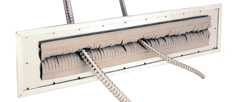
The correct answer, and the standard practice for genuinely shielded enclosures, is to bring all services through one controlled penetration — a single entry panel, or bulkhead, welded or gasketed into the shield and bonded to it around its entire perimeter. Every conductor that must enter the room enters there, and enters treated: each power line through its feed-through filter, each copper signal line through its filter or isolator, each fiber through its waveguide penetration, each pipe through its dielectric break, the air through its honeycomb vents nearby. The bulkhead is the one place in the shell where the inside world and the outside world are permitted to meet, and because it is one place, it can be engineered to a fare-thee-well and — just as importantly — inspected against a single schedule. A boundary with one treated crossing is auditable. A boundary with a hundred casual crossings is a rumor.

The physics that makes the single panel non-negotiable is the same slot-and-aperture physics from Volume 8. A shield works because it presents a continuous conductive surface on which the impinging field induces currents that cancel the field on the far side; the instant that surface is interrupted — by an unbonded seam, an ungasketed panel edge, or a conductor that passes straight through without termination — the induced currents have to detour around the discontinuity, and the discontinuity re-radiates. A conductor passing unfiltered through a shield is the worst case of all, because it does not merely interrupt the surface currents, it provides a low-impedance highway that couples the interior field directly to the exterior with essentially no attenuation. This is why the feed-through filter, discussed next, is not bolted to the inside face or the outside face of the panel but built into it, so the filter’s own case becomes part of the continuous shield and the “dirty” and “clean” sides of the conductor never share a volume in which they could couple. The bulkhead is the doctrine; the feed-through filter is the doctrine reduced to a component.
9.3 Power: the feed-through filter and the treated conductor
Line power is the hardest and most instructive of all the crossings, because power must enter — nothing in the room runs without it — and power conductors are, electrically, superb antennas and superb couplers. The mains wiring inside a facility is a dense web of copper running past every piece of equipment, and a compromising emanation does not have to radiate through the wall to escape; it can conduct straight onto the power conductors by capacitive and inductive coupling and ride the mains out of the building, where an adversary with a coupling clamp on the utility feed can look for it. This is the conducted-emanation problem, and its answer is the TEMPEST / EMI power-line filter.
A power-line filter is, at bottom, a low-pass filter: a lumped network of series inductors and shunt capacitors arranged to pass the mains frequency (50 or 60 Hz, plus the ordinary harmonics a real load draws) with negligible loss while presenting an enormous, rising attenuation to everything above a few kilohertz — the entire band in which compromising emanations live, from the low audio through the hundreds of megahertz and into the gigahertz. The good ones deliver on the order of 100 dB of insertion loss across a very wide band, which is to say they attenuate the unwanted spectrum by a factor of a hundred thousand in voltage while leaving the 60 Hz power essentially untouched. The filter does not care what the high-frequency energy is; it simply refuses to pass it, so a compromising signal that has coupled onto the mains inside the room dies at the filter and never reaches the conductor on the far side.
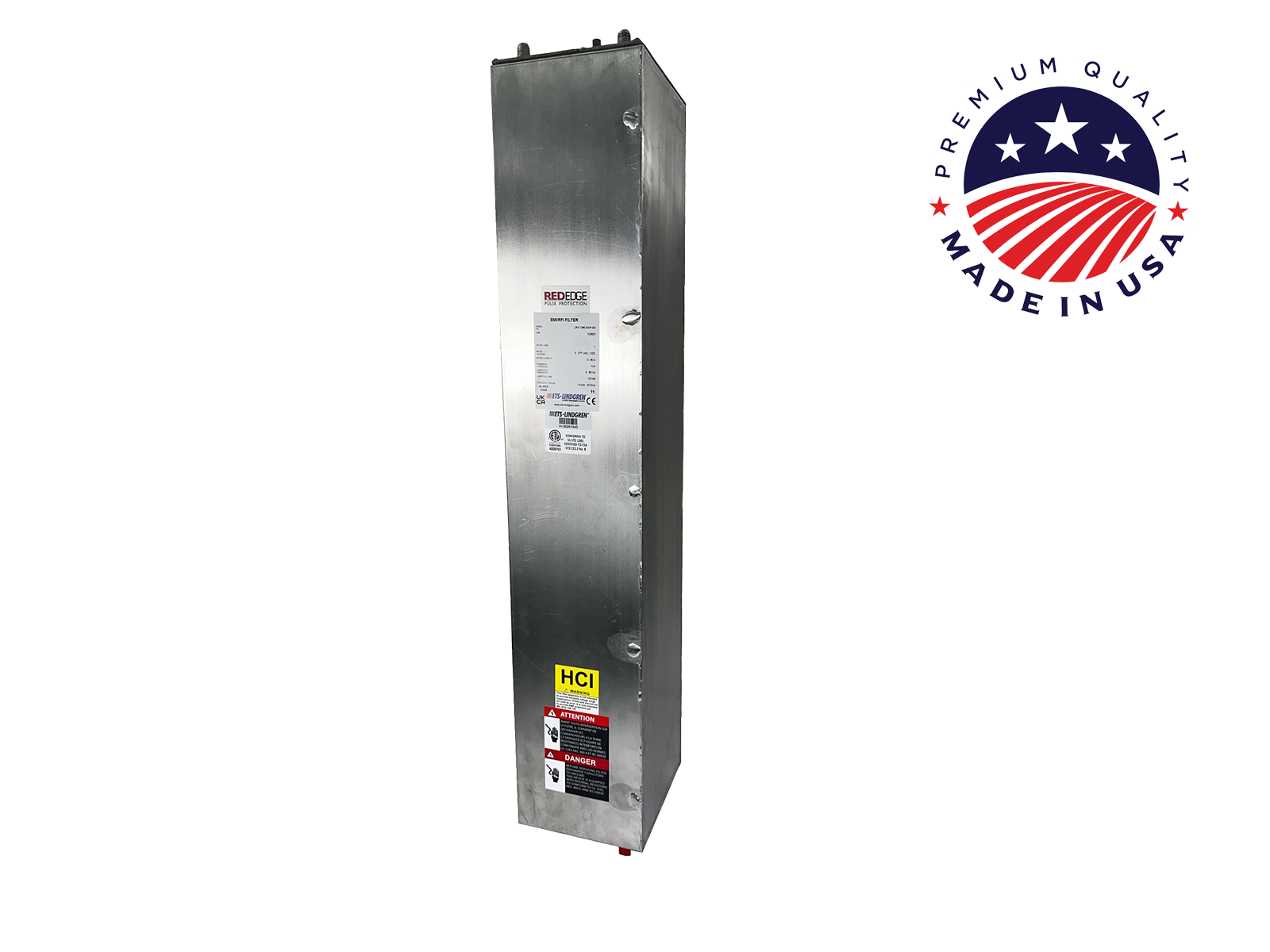
Three details separate a real TEMPEST power filter from the EMI line filter one might buy for a switching supply, and each is worth an engineer’s attention. First, it is a feed-through, mounted in the shield wall. The filter’s body is a conductive can bonded 360 degrees to the entry panel, the dirty (interior) terminal enters one shielded volume and the clean (exterior) terminal exits another, and the shield of the panel runs between them. This matters because a filter is only as good as its ground reference and its isolation: a superb filter network with its input and output terminals sharing an unshielded space will simply let the high-frequency energy jump the filter through the air, coupling around the very network meant to stop it. Building the filter into the shield forces every electron of the unwanted spectrum to attempt the filter and denies it any bypass path. This is the same logic as the single bulkhead, applied one conductor at a time.
Second, every current-carrying conductor is filtered — including neutral and, where the installation demands, the ground. This is the detail that trips up the uninitiated. A three-phase feed does not get its three phases filtered and its neutral run straight through; the neutral carries return current and can carry emanation just as readily as a phase, so it gets its own filter. The equipment-grounding conductor is treated with more nuance — grounding is its own section below — but the principle is uncompromising: a filter that treats three of four conductors has left one antenna un-cut. In a fully treated shielded SCIF the power enters as a bundle of individually filtered conductors landing on the entry panel, one filter can per conductor, which is why a shielded-room power-entry panel is a bank of filters rather than a single component.
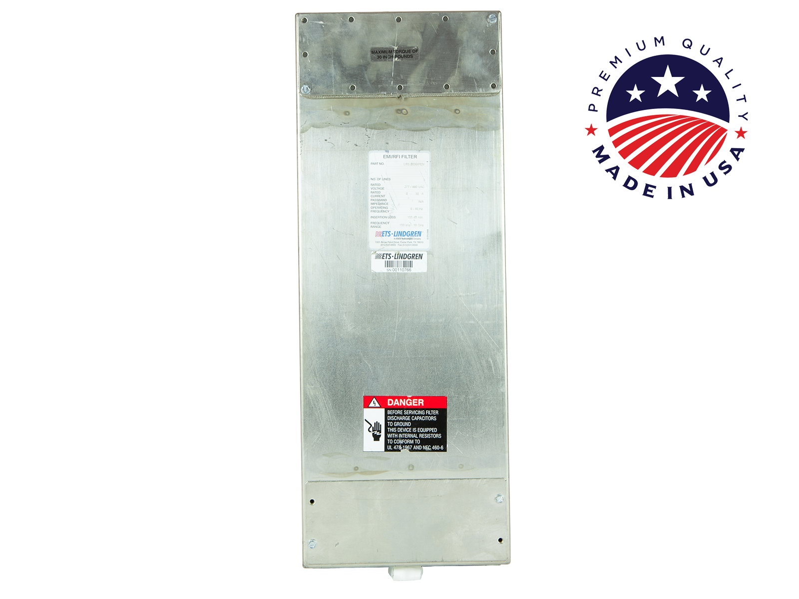
Third, the filter must be rated for the fault current and voltage of the circuit it sits in, and it must fail safe. A power-line filter carries the full load current of everything downstream of it, continuously, so it is a genuine power component with real thermal and fault ratings, not a signal trinket. Its shunt capacitors are line-to-ground, which means they leak a small current to the enclosure — the “leakage current” figure on the datasheet — and that leakage has to be reconciled with the facility’s grounding and with personnel-safety limits, one more reason the ground system and the filter selection are designed together rather than separately.
Above and around the filters sit two more power-conditioning ideas the SCIF borrows from ordinary sensitive-electronics practice but leans on harder. An isolation transformer — a transformer with separated primary and secondary windings and, ideally, a grounded electrostatic shield between them — breaks the direct metallic path from the utility to the room’s power, so that a signal capacitively coupled onto the mains does not conduct straight through; the interwinding shield gives that high-frequency energy a place to drain to ground rather than couple across. And RED/BLACK power separation governs the whole arrangement: equipment processing unencrypted classified information (RED) is fed from power that is kept separate from, and filtered against, the power feeding non-sensitive (BLACK) equipment, so that plaintext cannot modulate a shared mains and ride out on the BLACK side. The public framing of these rules lives in the old RED/BLACK engineering-installation guidance and the NSTISSAM family; as always, the logic is unclassified and the separation distances are not. The engineer’s takeaway is architectural: RED power and BLACK power are two systems that meet only at treated, filtered, grounded interfaces, never casually.
9.4 Grounding: the single reference
Grounding deserves its own section because it is the quiet foundation under everything else in this volume, and because the word “ground” is doing at least three different jobs that a careful engineer keeps separate. There is safety ground (the equipment-grounding conductor and the earthing system whose job is to keep exposed metal at earth potential and to clear faults — the National Electrical Code’s concern, and non-negotiable for life safety). There is signal ground / reference (the low-impedance conductor against which circuits measure their signals). And there is the shield itself (the Faraday envelope, which must be a single continuous conductive surface at a single potential). In an ordinary building these three are treated casually and often bonded together wherever convenient. In a shielded SCIF they are engineered deliberately, because grounding is simultaneously central to shielding effectiveness and to RED/BLACK, and getting it wrong defeats both.
The organizing concept is the single-point ground feeding an equipotential ground plane. The shield, the filter cases, the entry panel, the equipment racks, and the reference for the room’s electronics are all bonded to one ground system that establishes one reference potential throughout the space, and that system connects to the building’s earth-electrode subsystem at a single, controlled point. The reason is subtle and important: if two parts of the room are grounded to earth at two different points, any current flowing in the earth between those points (and there is always some — lightning, fault current, the ordinary noise of a building’s power system) develops a voltage between the two ground references, and that voltage appears across whatever equipment bridges them. Those ground loops are exactly the mechanism by which a low-level signal in one part of the room couples into another and, worse, by which a compromising emanation finds a return path onto a conductor headed for the boundary. A single reference point eliminates the loop: there is only one place the room’s ground touches the wider world, so there is no closed path through the earth for a difference current to flow.

The equipotential ground plane is the spatial version of the same idea: rather than a single wire, the reference is a sheet — the shield floor, a ground grid, or a copper mesh under the raised floor — so massive and so low in impedance that every point on it is at effectively the same potential even at high frequency, and every rack and cabinet bonds to it with the shortest possible strap. High frequency is the operative qualifier. A ground conductor that is a dead short at 60 Hz can be a significant impedance at 100 MHz, because a few feet of wire is a meaningful fraction of a wavelength and has real inductance; a compromising emanation lives up there, in the megahertz and gigahertz, so the ground system that matters for TEMPEST is the one that stays low-impedance at radio frequencies, which means short, wide, bonded straps to a plane — not long green wires to a bus bar. This is why shielded-room grounding looks so different from ordinary building grounding: it is designed against the RF the room is trying to contain, not just the fault current the room is trying to clear.
The relationship to the shield closes the loop. The shield must be a single continuous surface at a single potential; the single-point ground is that potential; the filters reference their attenuation to that ground; and RED/BLACK separation is, in part, a grounding discipline — RED equipment grounds and BLACK equipment grounds are arranged so that a plaintext signal cannot use a shared ground impedance as the common path that couples it onto a BLACK conductor. Grounding is not a utility afterthought in a SCIF. It is the reference against which shielding, filtering, and RED/BLACK are all defined, and it is designed first.
9.5 Copper’s problem, fiber’s answer
With power and ground handled, the room still has to move its actual work — the network traffic, the classified video, the telephone — across the boundary, and here the engineering makes a decisive turn. Copper data cabling suffers the identical disease as copper power: it is a conductor, so it radiates, it couples, and it carries conducted emanations. A classified network run on copper is a RED signal path, and a copper RED path leaving the room is precisely the thing the whole discipline exists to prevent. Copper can be made to cross the boundary — through signal-line filters that low-pass it the way the power filters treat the mains, through isolators and baluns, through opto-isolators that break the metallic path — but every one of those treatments is a compromise that costs bandwidth, adds a device to inspect, and leaves a conductor that is treated rather than absent. The signal-line filter is the copper answer, and it is a real and used answer, but it is playing defense against a medium that is fundamentally the problem.
Fiber optic is the medium that makes the problem disappear. An optical fiber is a dielectric — a strand of glass with no metallic conductor anywhere in it — so it cannot act as an antenna, cannot carry a conducted emanation, cannot couple a hostile injected signal, and cannot form a ground loop, because it has no conductor to do any of those things with. The information rides as modulated light confined inside the glass, and light does not leak an electromagnetic emanation the way a switching current on a copper pair does. For getting data across a shielded boundary, this is close to a free lunch, and it is why fiber is the modern default for the crossing: the RED-to-BLACK network path is carried on glass, and the glass carries no signature.
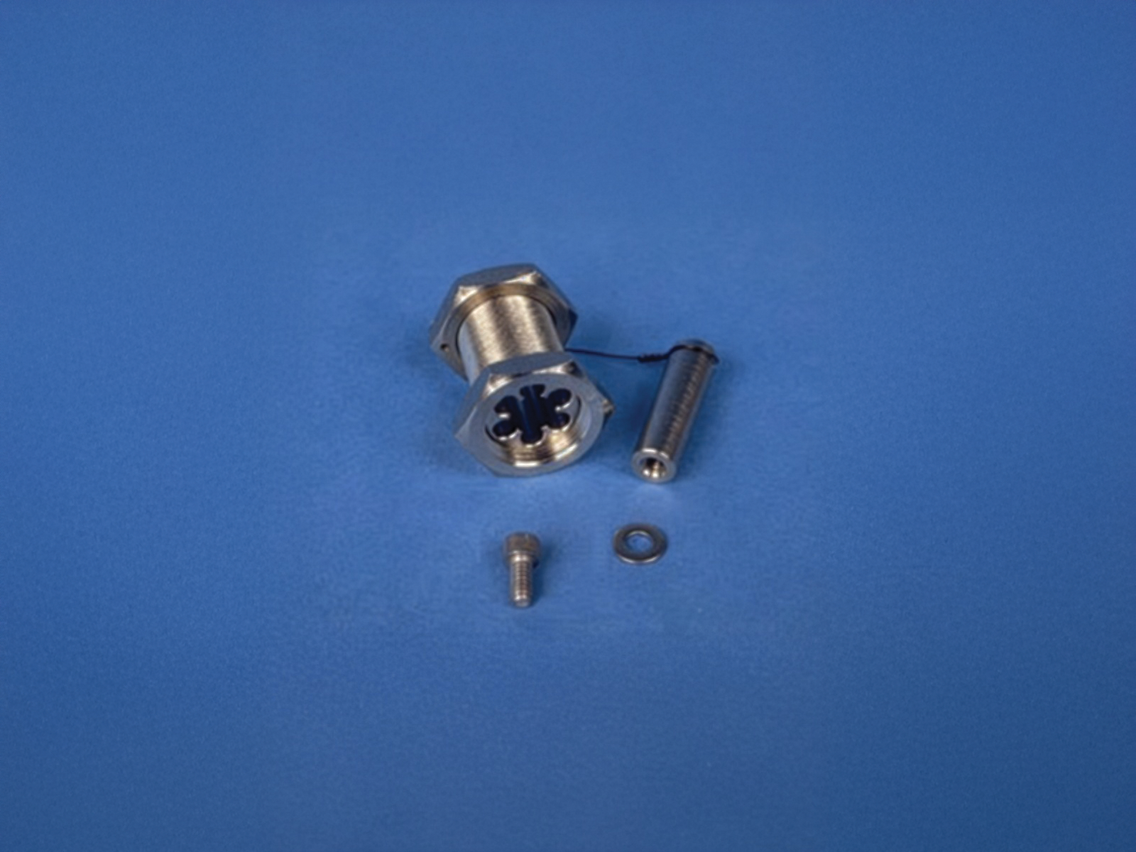
Fiber does not, however, escape the geometry of the boundary, and two honest caveats keep the engineer’s enthusiasm in check. First, the fiber still needs a penetration. A glass strand carries no current, but the hole it passes through is still a hole in the shield, and an untreated hole is an aperture regardless of what is (or is not) in it. The elegant solution reuses the physics from Volume 7’s honeycomb vent: the fiber passes through a waveguide below cutoff — a small metallic tube, bonded to the shield, whose diameter sets a cutoff frequency far above anything of concern, so the tube attenuates any field trying to use the opening while passing the dielectric fiber straight through. Because the fiber itself is non-conductive, it does not couple energy into the waveguide the way a wire would, so a below-cutoff tube plus a dielectric fiber is one of the cleanest crossings in the whole shell: the shield stays continuous, the aperture is a waveguide that attenuates rather than a slot that radiates, and nothing conductive bridges inside to outside.
Second, fiber is not automatically “black,” and history remembers why. Two concerns recur. An optical fiber can be tapped — bend it sharply and a little light escapes the core, enough for a sensitive detector to recover the data — so a classified fiber run through uncontrolled space is not inherently safe just because it is glass; it still wants physical protection or encryption (which is exactly the Protected Distribution System question of the next section). And the media converter — the box that turns the RED electrical signal into light and back — is itself a RED device: on its electrical side sits plaintext, with all the emanation and coupling concerns of any RED equipment, so the converter belongs inside the protected boundary, treated as RED, with only the glass leaving it. The fiber solves the conductor problem completely and the penetration problem elegantly; it does not by itself solve the plaintext-in-uncontrolled-space problem, which is a physical-protection or cryptographic question, and which is where the volume turns next.
9.6 Protected Distribution Systems: physical protection in lieu of crypto
Sometimes a classified signal has to travel, in the clear, through space the facility does not control — down a corridor shared with other tenants, between two buildings, across a floor that is not itself accredited. The signal is RED; the space is not trusted; encryption, for whatever reason, is not being used on that link. The doctrine’s answer to this specific, common situation is the Protected Distribution System (PDS): a hardened, inspectable carrier that provides physical protection to an unencrypted classified line in lieu of the cryptographic protection that would otherwise be required. The governing document is CNSSI No. 7003, “Protected Distribution Systems (PDS)” (September 2015), which descended from the earlier NSTISSI No. 7003 and, before that, the Cold-War-era guidance for what used to be called “approved circuits.” The idea is old and simple: if you are going to run plaintext through untrusted space, put it inside something an adversary cannot get into without being detected.
A PDS is, physically, the RED cabling (copper or fiber) enclosed in a carrier — most visibly, a run of rigid steel conduit — whose whole purpose is to make surreptitious access to the wire impossible, or at least impossible to accomplish without leaving evidence a scheduled inspection will find. CNSSI 7003 divides PDS into two families by the level of physical protection they provide. Hardened distribution systems give the most, and come in three forms: a hardened carrier, an alarmed carrier, and a continuously viewed carrier. Simple distribution systems give a reduced level of protection, appropriate to more controlled surroundings, using a simple carrier. The distinction is a classic security trade: the less you can trust the space the line runs through, the harder — and more actively monitored — the carrier has to be.
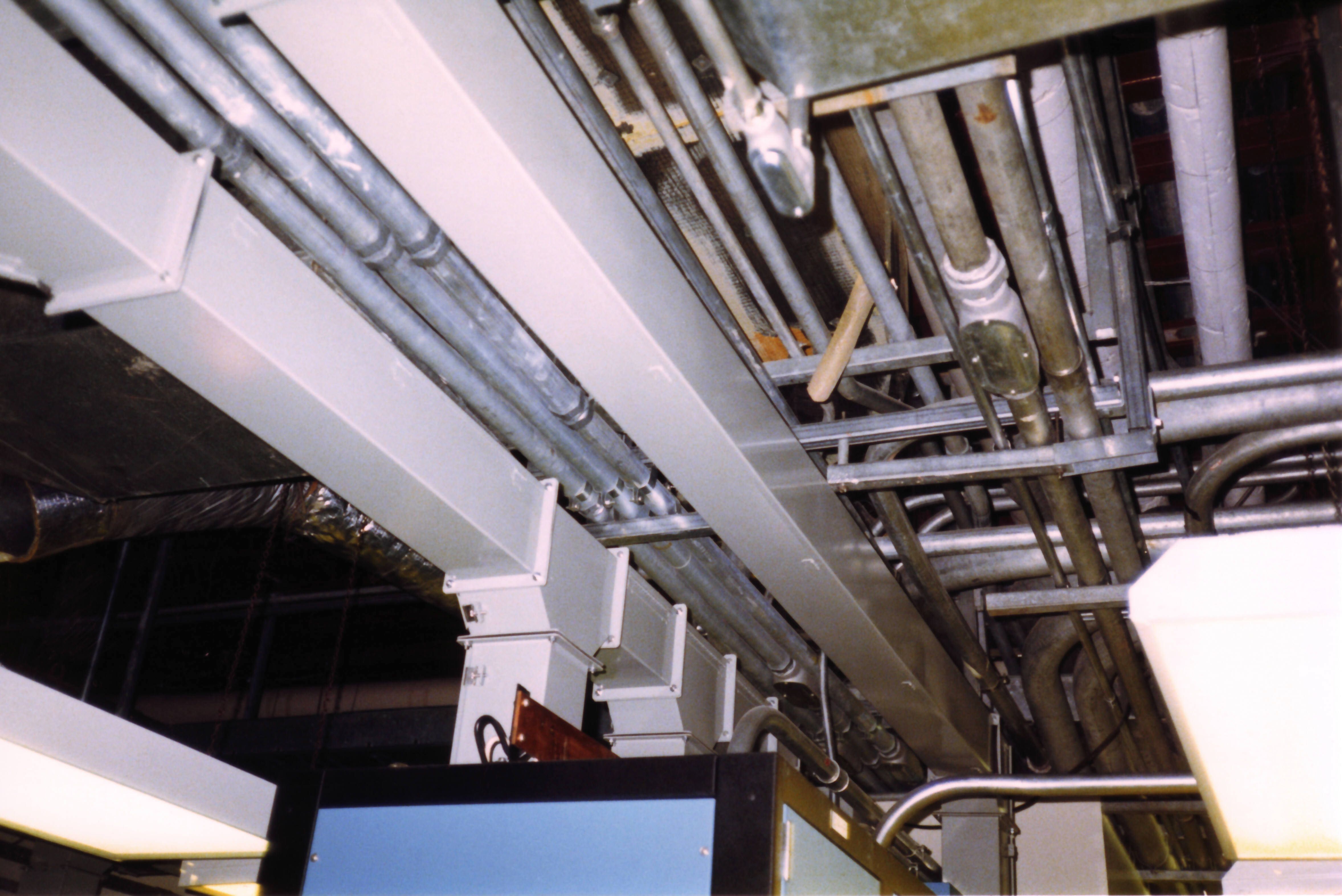
The construction rules for a hardened carrier are worth stating because they are unclassified, concrete, and characteristically strict. The carrier must be ferrous — electrical metallic tubing (EMT), ferrous pipe conduit, or ferrous rigid sheet-metal ducting; flexible conduit and armored cable are explicitly not acceptable, because they can be worked open and reclosed. Every connection that exists in the run must be permanently sealed around all mating surfaces by welding, epoxy, or fusion — a joint that can be unscrewed is a joint an adversary can open, so set-screw couplers are prohibited outright. Pull boxes and terminal boxes get locks and tamper-evident seals. An alarmed carrier adds electronic or fiber-optic intrusion detection so that any attempt to breach the carrier annunciates in real time, which buys the freedom to run it through less-controlled space or to inspect it less often; a continuously viewed carrier substitutes constant human or camera observation for the seal-and-inspect regime. A simple carrier relaxes the hardened-carrier rules for situations where the surrounding space is itself controlled enough to carry part of the burden.
Whatever the category, the entire model rests on inspection, because physical protection that is never checked is merely physical decoration. A PDS is walked and visually examined on a schedule (and randomly, to defeat an adversary who would time around a predictable one): the carrier, its connections, its lock boxes and pull boxes, its locks and its tamper-evident seals are all assessed for signs of penetration, tampering, or deterioration, and — a nice operational detail — the inspection is conducted from a distance close enough to detect an attempted intrusion, not merely a completed one. Every inspection is logged with date, time, and the inspector’s name and title, so that the protection is not just performed but auditable, which is the same theme as the penetration schedule of Volume 7: a control you cannot demonstrate you exercised is a control you do not really have.
And here is the key engineering decision the PDS poses, stated plainly, because it is a genuine trade an EE designing a facility will actually make: you can protect a classified line physically, or you can protect it cryptographically, and the two are alternatives. A PDS is what you build when you are going to send plaintext through untrusted space and must therefore make the space trustworthy — with steel, seals, alarms, and inspections. The alternative is to encrypt the link with NSA Type 1 cryptography, at which point the signal on the wire is ciphertext, the wire becomes a BLACK line, and it may be run through uncontrolled space as ordinary cabling with none of the PDS’s hardened-carrier apparatus — because there is nothing on it worth stealing. Encryption converts a physical-security problem into a key-management problem; the PDS converts it into a construction-and-inspection problem. Which one wins depends on the specific geometry and economics: a short run between two adjacent accredited spaces may be cheaper to armor in conduit than to bracket with crypto devices at each end, while a long run, or one crossing genuinely hostile ground, is almost always better encrypted so the wire can simply be treated as black. The modern tendency, as Type 1 encryption has become smaller and cheaper, leans toward “just encrypt it,” but the PDS remains the doctrinally sanctioned way to move plaintext through space you don’t own, and rigid steel conduit sealed at every joint is still a common sight for exactly that reason.
9.7 Air, water, and the dielectric break — a second look
Volume 7 walked the HVAC ducts, the sound baffles, the honeycomb vents, and the pipe penetrations as acoustic and forced-entry problems. This volume owes them a second look from the emanation angle, because from an RF standpoint every one of those openings is a hole in the Faraday shell, and the same physics that filters a power conductor governs how air and water are allowed through.
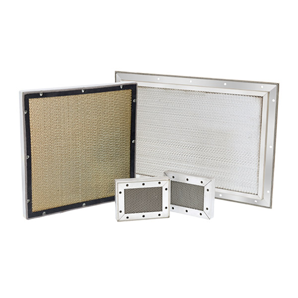
Air is the elegant case, because air is not a conductor and needs no filter — it needs a waveguide below cutoff, which the honeycomb vent supplies. Each metallic honeycomb cell is a short tube whose cross-section sets a cutoff frequency up in the tens of gigahertz; every frequency of practical concern falls far below that cutoff and is attenuated exponentially along the cell’s depth, so the panel passes air with modest pressure drop while delivering 80 to 100+ dB of shielding, provided — and this is the whole subtlety — its frame is bonded around its full perimeter to the shield, because an ungasketed frame edge is a slot antenna that undoes the honeycomb’s work. The honeycomb vent is the general solution for getting air through a shield, and (as the fiber section noted) a single scaled-up cell is also the general solution for getting a dielectric fiber through one. It is the same trick each time: make the aperture a waveguide that attenuates rather than a slot that radiates.

Water and the other pipes are the conductor problem in plumbing form. A metal water or sprinkler pipe running from inside a shielded SCIF to the outside is a conductor bridging the RED interior and the BLACK exterior — a ready-made path for conducted emanations and a possible injection route, exactly like an unfiltered wire. The countermeasure, introduced in Volume 7, is the dielectric break (or dielectric union): a non-conductive coupling inserted in the pipe where it crosses the boundary, interrupting the metallic path so the pipe cannot carry current across the shield even though it carries water across it perfectly well. The shield’s continuity is then maintained by a bonded penetration around the pipe rather than by the pipe itself. It is the plumbing analogue of the feed-through filter — let the water through, stop the current — and it is why a compliant shielded SCIF has a plastic or ceramic gap in its metal pipes right at the wall, a detail that looks like nothing and is doing real emanation-security work. The man-bars of Volume 7 (half-inch steel on six-inch centers for any opening over 96 square inches) still apply to the ducts as forced-entry protection; the point here is only that the same opening carries an RF treatment stacked on top of the acoustic and intrusion treatments — three problems solved in series on one hole, of which this volume owns the third.
9.8 Antennas: the controlled aperture
Every section so far has been about keeping signals from crossing the boundary except on tightly controlled terms. There is one category of service that inverts the whole premise: sometimes the SCIF’s job requires it to receive real radio-frequency signals from the outside world — satellite communications, GPS timing, or radio links whose entire purpose is to bring signal in and send signal out. A room built as a Faraday cage explicitly to keep RF from crossing its skin must now, on purpose, let specific RF cross its skin, and the tension between “sealed box” and “must receive RF” is real and unavoidable.
The resolution is to treat the antenna feed as a controlled aperture — a single, deliberate, bandwidth-limited crossing rather than an open window. The antenna itself lives outside the shield, where it is supposed to be, exposed to the sky it needs to see. Its feed line crosses the boundary at the entry bulkhead like every other service, and crosses it treated: through a feed-through in the shield, and typically through a band-limiting filter that passes only the intended operating band and rejects everything else, so the feed cannot become a wideband conduit carrying the room’s emanations out on the same coax that carries the wanted signal in. A GPS feed passes a narrow band around 1.575 GHz and nothing else; a SATCOM feed passes its assigned uplink/downlink bands and nothing else. The filter turns the antenna port from a generic hole in the shield into a narrow, defined pipe that admits exactly the wanted signal and attenuates the compromising spectrum that would otherwise ride the same conductor.
The engineering honesty here is that this is a managed compromise, not a clean win. Any deliberate RF aperture is, by definition, a reduction in the shield’s perfection at the frequencies it must pass, and the design accepts that reduction in exchange for the mission the antenna serves — while confining it to the narrowest band, the single location, and the most tightly filtered feed the requirement allows. It is the same philosophy as everything else in the volume, applied to the one service whose whole point is to cross: minimize the crossing, treat it at one controlled place, and give it exactly as much aperture as the mission demands and not one hertz more.
9.9 The wireless prohibition
The controlled-aperture antenna is the authorized exception. The far larger category is the prohibited one, and it is worth stating clearly because it is the single most visible rule of SCIF life: personal electronic devices (PEDs) — cell phones, smartwatches, fitness bands, wireless earbuds, laptops with radios, anything that transmits — are generally forbidden inside a SCIF, and deliberate wireless of any kind is, at best, tightly and specifically controlled. The bin of surrendered phones outside the door is the everyday face of everything this series has argued.
The reasoning falls straight out of the previous eight volumes. A transmitting device inside the shielded volume is an uncontrolled emanation source on the wrong side of the boundary — the very thing the shield exists to contain, brought inside it by the person carrying it. Worse, a modern smartphone is a nearly ideal covert exfiltration platform: it has microphones, cameras, storage, and several radios, and if it were compromised (or simply operated by someone it should not be) it could record a classified conversation and carry the recording out in a pocket, or — more insidiously — modulate some emanation to leak data across the boundary the facility spent a fortune sealing. The rule against PEDs is not institutional paranoia; it is the recognition that a wireless device inside the shield defeats, in one stroke, both the emanation containment and the physical-media control that the entire facility is built to enforce. Where deliberate wireless is permitted — a specific, accredited wireless intrusion-detection sensor, say, or an authorized system operating under its own approval — it is the exception that proves the rule: enumerated, risk-assessed, accredited, and constrained, never casual. The default is no radios, because a radio is a penetration that walks through the door on its own two feet.
9.10 Tracing one connection from desk to the world
Abstractions are easier to trust once they are walked end to end, so consider a single, concrete path: a classified workstation sitting on a desk inside a shielded SCIF, and the journey its network traffic takes to reach the outside world. Following one connection through the whole apparatus ties every section of this volume into a single line.
The workstation is a RED device: the data on its screen and in its interfaces is unencrypted classified information. Its network connection does not leave the machine on copper if the design is clean; it leaves on fiber, converted from RED electrical signaling to light by a media converter that sits inside the protected boundary and is itself treated as RED equipment — plaintext on its electrical side, glass on its optical side. From the converter, the fiber runs to the room’s entry bulkhead, the single controlled crossing where every service meets the shield. There the fiber passes through a waveguide-below-cutoff penetration — a small bonded metallic tube that keeps the shield continuous while letting the dielectric strand through, coupling nothing because the strand carries no current. On the far side of the bulkhead the glass is in a different world, and one of two things happens to it, per the trade of the PDS section. Either the classified link is encrypted by an in-line NSA Type 1 device, after which the outbound fiber is a BLACK line carrying ciphertext and may run onward through uncontrolled space as ordinary cabling; or, if it must travel as plaintext through space the facility does not control, the fiber is enclosed for that leg in a Protected Distribution System — a hardened carrier of sealed ferrous conduit, inspected on a logged schedule — until it reaches the next accredited space.
Meanwhile, the same desk’s power has made the mirror-image journey in reverse: from the utility, through an isolation transformer, onto the RED power system, through a bank of feed-through filters at the entry bulkhead — every conductor including neutral individually filtered — and only then to the outlet under the desk, so that whatever compromising spectrum the workstation impresses on its mains dies at the filter and never reaches the utility. Both journeys reference the same single-point ground: the workstation, the media converter, the filter cases, the shield, and the entry panel all bond to one equipotential plane that touches the earth at exactly one controlled point, so no ground loop offers a difference current a path across the boundary. In that one traced connection sit the fiber-over-copper preference, the waveguide penetration, the RED/BLACK crossing, the encrypt-versus-PDS decision, the filtered power, and the single ground — the whole volume, running under one desk.
9.11 The design philosophy in one breath
Strip away the components and the same five instincts govern every crossing in this volume, and they are worth holding onto as the thing to remember when the datasheets blur together. Minimize the penetrations — the cheapest treated hole is the one never cut, so the design fights for every service it can consolidate or eliminate. Bring the survivors through one controlled place — the single entry bulkhead, bonded to the shield, where every crossing can be treated identically and inspected against one schedule, because a boundary with one seam is auditable and a boundary with a hundred is a hope. Treat every conductor that crosses — filter the power (all of it, neutral included), filter or isolate the copper, break the pipes with dielectric unions, waveguide the air and the fiber, because a conductor left untreated is an antenna soldered to the shield. Reference everything to one ground — a single-point, equipotential, RF-quiet reference, so that shielding, filtering, and RED/BLACK are all defined against one potential and no ground loop bridges inside to out. And prefer the dielectric and the encrypted crossing to the metallic one — fiber over copper because glass has no conductor to compromise, and ciphertext over plaintext because a black line has nothing worth stealing, so the strongest crossing is the one that carries no exploitable signal in the first place.
That is the payoff the whole series was building toward. Volumes 6 and 7 made the box continuous; Volume 8 made it, where required, a Faraday cage; and this volume is how that cage becomes a room a person can actually work in — power humming, air moving, fiber lit, phone live — without any of it becoming the one worst hole that gives the whole investment away. The door of Volume 7 lets the people through on controlled terms; this volume lets the electrons and the photons through on exactly the same terms — in, but never carrying anything back out. What remains, in Volume 10, is the discipline that keeps all of it honest over a facility’s operational life: the access control, the alarms, the inspections, and the accreditation that turns a well-built box into a trusted one.
Sources
- Committee on National Security Systems, CNSSI No. 7003, Protected Distribution Systems (PDS) (September 2015) — the governing public standard: PDS definition; hardened distribution systems (hardened carrier, alarmed carrier, continuously viewed carrier) vs. simple distribution systems; hardened-carrier construction (ferrous EMT/conduit/ducting, no flexible conduit or armored cable, all connections sealed by welding/epoxy/fusion, no set-screw couplers); inspection and logging regime. Descended from NSTISSI No. 7003 (1996). Public copy via DCSA: https://www.dcsa.mil/Portals/91/documents/ctp/nao/CNSSI_7003_PDS_September_2015.pdf ; NSTISSI No. 7003 (13 Dec 1996): https://fiswg.research.ucf.edu/Documents/PDF/NSTISSI%20No.%207003.pdf
- Defense Counterintelligence and Security Agency, Protected Distribution System Checklist (12 October 2016) — the all-purpose PDS inspection/construction checklist (carrier construction, sealed joints, pull/terminal boxes, inspection log contents). https://www.dcsa.mil/Portals/91/documents/ctp/nao/PROTECTED_DISTRIBUTION_SYSTEM_CHECKLIST-October_12_2016.pdf ; DISA Traditional Security Checklist PDS findings (STIG Viewer), e.g. hardened/alarmed/continuously-viewed carrier requirements: https://www.stigviewer.com/stigs/traditional_security_checklist/2024-08-09/finding/V-245729
- ODNI / National Counterintelligence and Security Center, IC Tech Spec for ICD/ICS 705 v1.5.1 (26 July 2021) — SCIF perimeter penetration criteria, the single-point/consolidated service entry philosophy, TEMPEST countermeasures determination by the CTTA, and the acoustic/pipe/duct penetration treatments revisited here from the RF angle. https://www.dni.gov/files/NCSC/documents/Regulations/IC_Technical_Specifications_for_Construction_and_Management_of_Sensitive_Compartmented_Information_Facilities_v151_PDF.pdf
- CNSS / NSTISSAM TEMPEST family and RED/BLACK engineering-installation guidance (MIL-HDBK-232 lineage) — the RED/BLACK separation, filtered-power, and segregated-grounding concepts (logic public; separation distances and emanation limits classified). Referenced for framing only; no classified constants used.
- Astrodyne TDI — TEMPEST / EMI power-line feed-through filters: feed-through low-pass construction, mounting in the shield wall, per-conductor (including neutral) treatment, high wideband insertion loss, load-current/leakage ratings. https://www.astrodynetdi.com/tempest-emi-filters and store: https://store.astrodynetdi.com/emi-filters/tempest.html
- API Technologies / Spectrum Control and MPE Ltd (mpe.co.uk) and Schaffner — additional TEMPEST/EMI power-line and signal-line filter product literature (feed-through filter cans, filtered power-entry panels/filter banks). https://www.mpe.co.uk/products/tempest-filters/ ; https://www.schaffner.com/
- ETS-Lindgren — shielded-enclosure engineering: EMI/RFI shielded waveguide air vents (honeycomb below-cutoff), filtered power-entry panels, and fiber-optic / waveguide penetrations for shielded rooms. https://www.ets-lindgren.com/products/components/shielding-components ; waveguide air vents: https://www.ets-lindgren.com/product/emi-rfi-shielded-waveguide-air-vents/
- Holland Shielding Systems — power entry panels, waveguide penetrations, fiber-optic feed-throughs, and EMI gaskets/fingerstock for shielded rooms. https://hollandshielding.com/
- MAJR Products — honeycomb waveguide vent panels, waveguide tubes, and EMI shielding components (below-cutoff attenuation, perimeter bonding). https://www.majr.com/product/honeycomb-waveguide-panels/
- Select Fabricators and Raymond EMC — modular RF/EMI shielded enclosures and their power-entry / penetration hardware (room-within-a-room construction, single-point filtered entry). https://www.select-fabricators.com/rf-shielded-products/ ; https://raymondemc.com/
- IEEE Std 299, Standard Method for Measuring the Effectiveness of Electromagnetic Shielding Enclosures — the public method by which the treated boundary (including its penetrations) is verified in dB. https://standards.ieee.org/ieee/299/1728/
- MIL-STD-188-125-1/-2, HEMP Protection for Ground-Based C4I Facilities — public standard whose points-of-entry protection philosophy (every penetration treated at a single, bonded, filtered boundary) parallels the emanation-security treatment described here. https://quicksearch.dla.mil/qsDocDetails.aspx?ident_number=36097
- Henry W. Ott, Electromagnetic Compatibility Engineering (Wiley, 2009) — grounding (single-point vs. multipoint, equipotential plane, ground loops), filter theory, and the RF-frequency behavior of ground conductors underlying the grounding and filtering sections.
- Wikipedia, Protective distribution system — public overview of PDS categories and the physical-protection-in-lieu-of-encryption concept. https://en.wikipedia.org/wiki/Protective_distribution_system
Comments (0)