Scif · Volume 6
Anatomy and Construction I: The Shell
6.1 The box before the box
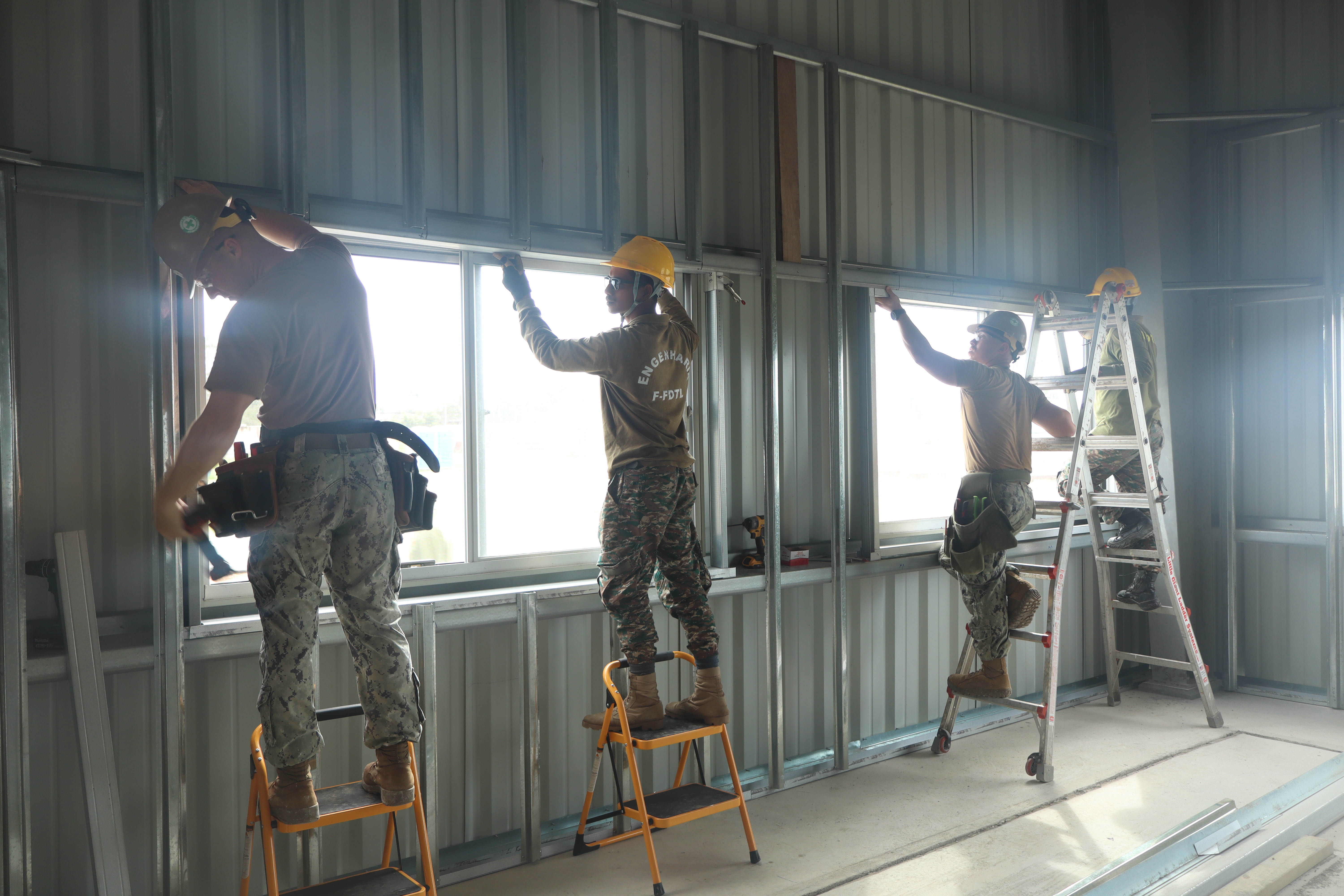
The previous volumes walked the history and the paperwork: why the SCIF exists, what it defends against, and which documents govern it. This one and the two that follow finally pick up a trowel. The question is deceptively simple — how is the box actually built? — and the honest answer is that the box is built twice. It is built first on paper, as a design package that an Accrediting Official reviews and approves before a single stud is set, and only then is it built in space, as an assembly of studs, gypsum board, expanded metal, sealant, and slab. Skipping the paper version is not merely a procedural sin; it is structurally impossible, because the drawings are what the accreditation is granted against. A SCIF that was framed before its design concept was approved is, in the eyes of the Accrediting Official, a very expensive ordinary room.
So this volume treats the shell as the standard treats it: as a lifecycle that starts in a design review and ends at the true ceiling. It covers the pre-construction package first — concept approval, the Construction Security Plan, the Fixed Facility Checklist, the drawing set, and the TEMPEST addendum — because that is the sequence a real project follows and because the reader asked, reasonably, to see the blueprints. Then it takes up the physical shell in the order the IC Tech Spec does: the perimeter as a continuous boundary, the lettered wall types, the floor and ceiling, and the acoustic performance that ties them together. It closes on the two ideas that make the shell more than carpentry — cleared materials and labor, and inspectable space — and on the uncomfortable truth that governs everything in Volume 7: a perimeter is only as good as its holes, and a SCIF is nothing but a box full of deliberate holes.
Throughout, the primary source is the public, unclassified IC Tech Spec for ICD/ICS 705, Version 1.5.1 (26 July 2021), whose Chapter 3 (Fixed Facility SCIF Construction) and Chapter 9 (Acoustic Protection) contain the wall sections, sound groups, and construction figures reproduced and paraphrased here. The Tech Spec’s construction drawings are U.S. Government works in the public domain, which is why an engineer can study them at leisure without a clearance.
6.2 The design package: a SCIF on paper
A fixed-facility SCIF is born as a proposal, and the first gate it passes through is concept approval. Before design money is committed, the sponsoring organization brings the Accrediting Official a description of what it wants to build and where, and the AO decides whether the concept is worth pursuing at all — whether the location, the intended use, and the surrounding environment can plausibly be made to meet the standard. Chapter 3 of the Tech Spec is explicit that the AO’s job includes reviewing and approving the design concept, the Construction Security Plan, and the final design prior to the start of SCIF construction. Concept approval is the cheapest place to say no, and a competent AO uses it.
Once the concept survives, the package accretes around it. The central planning artifact is the Construction Security Plan (CSP), developed by the Site Security Manager (SSM) in consultation with the AO. The CSP is not a building spec; it is the security narrative for the construction process itself — a document that, in the Tech Spec’s phrasing, must capture the actions required to document the project from start to finish. It names who is cleared and who is not, how the site is controlled, how construction materials and equipment are inspected and protected, how non-cleared workers are monitored, and how deviations are recorded and reported to the AO (within three business days, the spec says, which tells you how seriously the paperwork is taken). The CSP exists because the single most dangerous moment in a SCIF’s life is while it is being built: the walls are open, the conduit runs are exposed, and anyone with access to the site has a chance to introduce something that will never be found once the drywall goes up. The CSP is the discipline that closes that window, and it is the direct lineal descendant of the lessons of the Moscow embassy, to which this volume returns.
The Fixed Facility Checklist (FFC) is the other master document, and it plays the opposite role. Where the CSP governs the process, the FFC describes the product. It is the standardized descriptive record of the finished facility — its location, its perimeter construction, its doors and locks, its intrusion-detection and access-control systems, its acoustic treatment, its storage accreditation — filled out in the form the AO reviews for accreditation. In practice the FFC is the spine of the accreditation package; nearly every construction decision in this volume ends up as a line item on it. When the spec notes that a fastening method “shall be noted in the FFC,” or that a high-security lock on an inspection port “shall be noted in the FFC,” it is reminding the builder that the checklist is the permanent record and that undocumented deviations do not exist as far as accreditation is concerned.
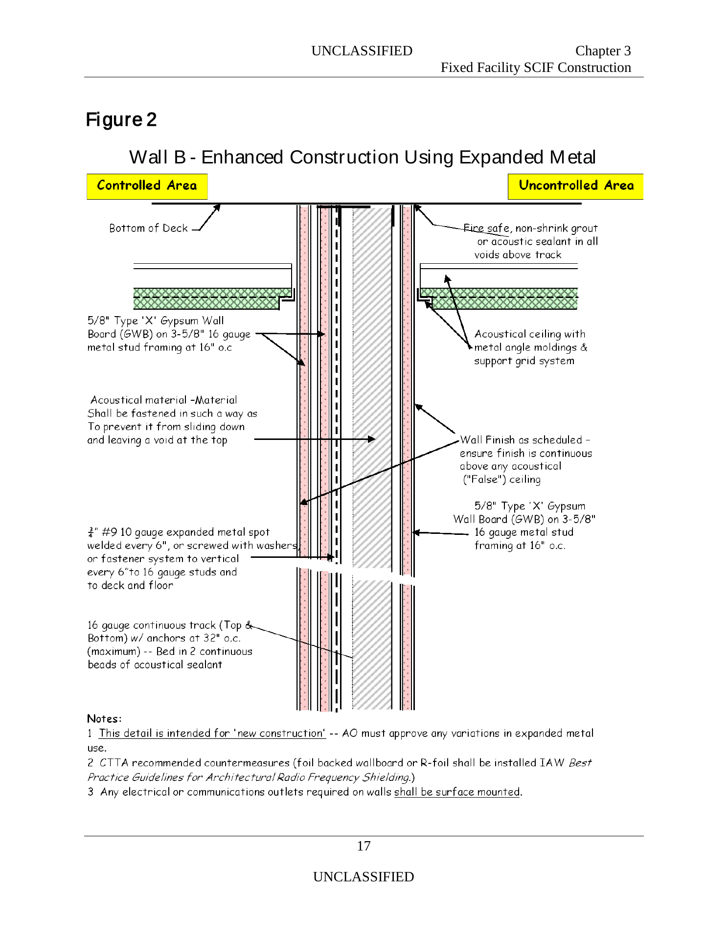
Where emanation security is in play, the package grows a TEMPEST addendum — the TEMPEST checklist that accompanies the FFC and feeds the Certified TEMPEST Technical Authority’s countermeasures determination. The addendum is where the facility’s electronic-processing profile, its RED/BLACK layout, and its relationship to the inspectable-space boundary get documented so the CTTA can decide what shielding, filtering, and separation the room actually needs. Volume 8 takes emanation security apart in earnest; here it is enough to note that the TEMPEST addendum rides along with the rest of the design package and that its outputs land back on the wall sections as notes like the one visible on the Wall B drawing: CTTA-recommended countermeasures (foil-backed wallboard or R-foil) shall be installed in accordance with the Best Practices Guidelines for Architectural Radio Frequency Shielding.
What, concretely, is on a SCIF drawing set? The same things that are on any commercial interior-construction set, plus a security overlay. The perimeter is drawn as a closed boundary and annotated with the wall type at each run. There is a penetration schedule — every place a duct, pipe, conduit, or cable crosses the perimeter, with its treatment called out — because in a SCIF a penetration is a security event, not a plumbing detail. There is a door schedule identifying the primary entrance, any secondary or emergency doors, and their hardware (the GSA-approved locks, closers, and access-control devices that Volume 7 and Volume 10 take up). There is an IDS/ACS layout showing where the intrusion-detection sensors and access-control readers go. And there are the construction detail drawings — the wall sections, the deck and floor details, the duct penetrations — that a framer and a drywall crew build from. The rest of this volume is essentially a reading of those detail drawings.
6.3 The perimeter: true floor to true ceiling
The single most important idea in SCIF construction is also the simplest to state and the easiest to violate: the SCIF perimeter is a continuous physical boundary that runs from the true floor to the true ceiling. The Tech Spec defines the SCIF perimeter as all the walls that outline the SCIF’s confines, together with its floors and ceilings, and it requires the wall assembly to be built — and finished, and painted — from the true floor slab to the true ceiling structure, not merely to the height of whatever suspended ceiling the occupants will see.
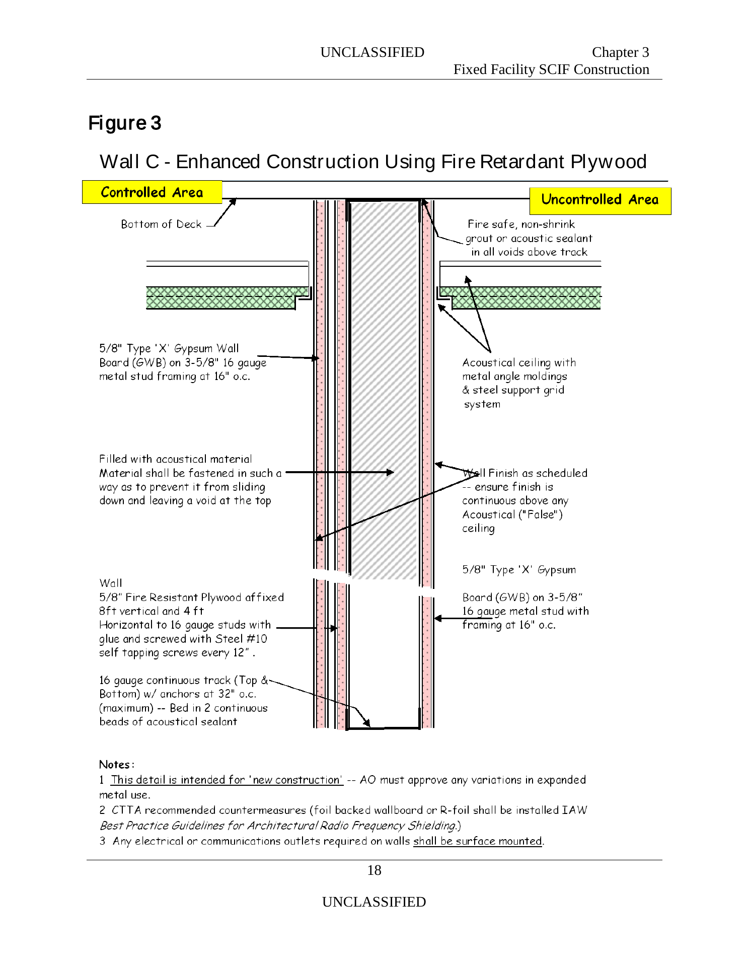
The distinction between the true ceiling and the finished ceiling is where amateurs get into trouble. Most commercial interiors are built to a suspended acoustic-tile ceiling hung a foot or two below the structural deck, with the space above — the plenum — used to run ducts, cables, and sprinkler pipe. If a SCIF’s security perimeter stopped at that grid, an intruder or an eavesdropping device could simply go over the top: lift a ceiling tile in the uncontrolled space next door, crawl the plenum, and drop into the SCIF above its “wall.” The Wall B and Wall C drawings make the correct construction unmistakable — the studded, sheathed wall continues past the acoustical ceiling all the way up to the bottom of deck, the finish is required to be continuous “above any acoustical (false) ceiling,” and the voids above the top track are packed with fire-safe non-shrink grout or acoustic sealant. The suspended ceiling is a convenience hung inside the box; it is emphatically not the box.
The same logic runs downward. A raised access floor — the pedestal-and-panel system common in data centers and briefing rooms, which hides cabling and cooling in the void beneath — is likewise inside the perimeter, not the perimeter itself. The structural slab is the true floor and the true floor is the boundary. A raised floor whose void communicates with uncontrolled space below or beside the SCIF is exactly the same threat as an open plenum overhead, and it is treated the same way: the void is bounded, inspected, and never allowed to become an unwatched crawlspace. The perimeter, in short, is a six-sided continuous shell — four walls, a true floor, and a true ceiling — and the drop ceiling and raised floor are furniture installed within it. Every later problem in this deep dive, from acoustic leakage to RF egress to forced entry, reduces to keeping that six-sided shell continuous and accounting for every place something has to pass through it.
6.4 The wall menu: types A, B, and C
The Tech Spec does not leave perimeter walls to the architect’s imagination. It publishes a small menu of standardized assemblies, lettered for convenience, each a specific stack of studs, gypsum board, and — in the hardened variants — expanded metal or plywood, matched to a required combination of acoustic and forced-entry performance. Getting the letters straight matters, because the choice between them is a security decision the AO signs off on, not an aesthetic one.
Wall A — the standard acoustic wall — is the baseline and the one most SCIFs use. It is three layers of 5/8-inch Type “X” gypsum wall board over 3-5/8-inch, 16-gauge metal studs at 16 inches on center: one layer on the outside (uncontrolled) face and two layers on the inside (SCIF) face, with sound-attenuation batts filling the stud cavity. The top and bottom tracks are bedded in continuous beads of acoustic sealant where they meet the slab and deck, and every penetration is treated and sealed. Wall A is the Tech Spec’s recommended construction for closed storage with Security-in-Depth, and its whole design intent is acoustic: the asymmetric two-plus-one gypsum layering and the cavity fill exist to drop intelligible speech below the level at which it can be reconstructed at the perimeter. What Wall A is not designed to do is resist a determined person with a tool; three layers of gypsum on studs is a sound barrier, not a safe.
For that, the spec offers two hardened variants, and both are aimed at the same target: five minutes of forced-entry resistance at the perimeter, the standard invoked for open storage without Security-in-Depth and wherever else the AO requires it.
Wall B — enhanced construction using expanded metal — takes the Wall A gypsum stack and adds a layer of 3/4-inch mesh, #9 (10-gauge) expanded metal to the interior side of the studs. The expanded metal is spot-welded to each vertical stud every six inches, and to the deck and floor, or (as an alternative the spec permits) fastened with hardened screws through one-inch washers or hardened clips at the same six-inch spacing. The point is penetration resistance: a sheet of steel diamond mesh welded to the framing turns a wall that could be breached with a utility knife and a few minutes’ patience into one that resists a saw, a drill, and a boot. Crucially, the drawing carries a note that expanded metal does not improve the acoustic rating — it is a forced-entry countermeasure layered onto an assembly that is already acoustically adequate. Wall B is also flagged as intended for new construction, with the AO required to approve any variation in how the expanded metal is used, because retrofitting steel mesh into an existing wall without opening it up is a fiction.
Wall C — enhanced construction using fire-retardant plywood — reaches the same five-minute forced-entry standard by a different route. It uses two layers of 5/8-inch Type “X” gypsum board (one outside, one inside) plus one layer of 5/8-inch fire-retardant plywood attached vertically and directly to the studs — the plywood substituting for one of the interior gypsum layers relative to the standard acoustic wall. The plywood is continuously glued and screwed to the studs every twelve inches, and the studs may be 3-5/8-inch metal or wooden 2×4 at a maximum of 24 inches on center. Where Wall B resists entry with steel mesh, Wall C resists it with a bonded structural-plywood diaphragm; both are acceptable, and the choice often comes down to what the crew can execute cleanly and what the RF and fire requirements favor. (Fire-retardant treatment is not incidental — the plywood is buried inside a life-safety-rated assembly, and the building code does not grant SCIFs an exemption from burning down.)
A note on nomenclature, since the field is inconsistent about it: the current Tech Spec’s perimeter wall menu runs A, B, and C. Older editions, vendor literature, and various training decks sometimes speak of additional lettered types or fold vault construction into the same alphabet, so a reader will encounter “Wall D” and beyond in secondary sources. The governing v1.5.1 document, however, standardizes the three perimeter assemblies above and then treats anything harder — true open-storage vaults — as a separate construction category rather than a fourth wall letter. The important engineering content is not the letter but the logic: a baseline acoustic wall (A), and two ways to bolt forced-entry resistance onto it (B with steel, C with plywood).

Two properties of the lettered menu are worth an engineer’s attention. First, the assemblies are not prescriptive to the exclusion of alternatives: the spec repeatedly allows other constructions — solid masonry, concrete, cinderblock — provided they meet the same acoustic and forced-entry performance and are approved by the AO. The letters are validated recipes, not a closed set; an eight-inch reinforced-concrete wall obviously satisfies the forced-entry requirement without any diamond mesh. Second, the two performance axes — acoustic and forced-entry — are largely independent, which is why Wall B can add steel without changing the sound rating and why the acoustic requirement is specified separately, in its own chapter, as a Sound Group. The wall type buys intrusion resistance; the Sound Group buys speech containment; and the two are dialed in more or less orthogonally.
6.5 Floors, ceilings, and the space above the grid
The Tech Spec dispatches floors and ceilings in a single crisp requirement — they shall be constructed to meet the same standards for force protection and acoustic protection as walls — and keeps their penetrations to a minimum. That one sentence carries a lot of weight, because it means the true floor slab and the true ceiling deck are not passive surfaces the walls happen to meet; they are two of the six faces of the perimeter and are held to the same forced-entry and acoustic bar as the vertical assemblies.
For a slab-on-grade SCIF the true floor is the building’s structural concrete, and it needs no special treatment to resist entry from below — nobody is tunneling through grade-level slab in the threat models the standard addresses. The problem gets interesting on upper floors and above suspended ceilings, where the “true” surface is a structural deck with uncontrolled space on the other side. There the ceiling must be brought up to wall standard: the perimeter walls carry past the acoustical grid to the underside of the deck, the deck itself must present a forced-entry and acoustic barrier equivalent to the walls, and any access hatch, duct, or cable tray crossing it becomes a scheduled penetration with its own treatment. The recurring failure mode, again, is treating the visible ceiling as the boundary and leaving the real deck unaddressed — the plenum-crawl attack described earlier is a ceiling failure as often as a wall failure.
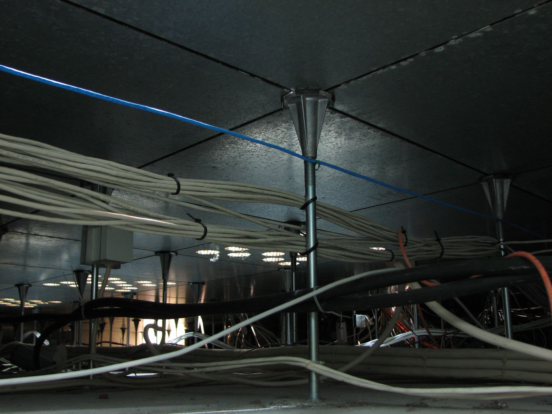
Raised access floors deserve the same suspicion as suspended ceilings, and for the same reason. The pedestal-and-panel void is a superb place to hide cabling and cooling — and, precisely because it is a hidden, continuous, walkable space, a superb place to hide a microphone, a cable tap, or a route into the room. The doctrine is symmetrical with the ceiling: the structural slab beneath the pedestals is the true floor and the boundary; the void above it is interior space that must be bounded so it cannot reach uncontrolled areas, and that must be inspectable — physically accessible for periodic examination — rather than sealed and forgotten. Under-floor inspection is a real recurring task, not a one-time construction check, because a void you cannot look into is a void an adversary is free to use. The same is true of the above-ceiling space: the reason the finish is required to be continuous above the false ceiling, and the reason penetrations are minimized and scheduled, is so that the concealed spaces of the SCIF remain few, bounded, and open to inspection.
6.6 Acoustic protection: Sound Groups, STC, and the amplified-speech problem
Acoustic containment gets its own chapter (Chapter 9) because it is a genuinely separate engineering problem from forced entry, and it is the one an EE reader will find most familiar: a transmission-loss problem dressed in security vocabulary. The whole objective is to ensure that speech inside the SCIF cannot be understood outside it — not merely muffled, but rendered unintelligible at the perimeter to an unaided ear.
The Tech Spec rates a perimeter’s speech-containment ability with the Sound Transmission Class (STC), the single-number ASTM rating (per ASTM E413, from laboratory transmission-loss measurements under ASTM E90) that summarizes how much airborne sound a partition attenuates across the speech band. It then organizes the requirement into Sound Groups. The two that dominate SCIF practice are:
- Sound Group 3 — STC 45 or better. The standard’s own description: loud speech from within the SCIF can be faintly heard but not understood outside it, and normal speech is unintelligible at the perimeter. This is the baseline the SCIF perimeter is designed and constructed to meet.
- Sound Group 4 — STC 50 or better. Applied where amplified audio is present — conference centers, briefing rooms, video-teleconference suites — because very loud or amplified sound is a harder containment problem. Areas that host amplified conversations must meet Sound Group 4.
The gap between STC 45 and STC 50 sounds small and is not. An additional five points of STC is roughly the difference between a wall that comfortably defeats a conversation and one that also defeats a loudspeaker, and it is bought with real material: the Wall A drawing notes that a Sound Group 4 wall requires four layers of 5/8-inch gypsum board and a special acoustic door or vestibule, rather than the three layers and standard door that satisfy Sound Group 3. This is mass law made bureaucratic — you buy transmission loss with surface density, and the extra gypsum layer is the surface density. The reason the standard draws the line at “amplified” is precisely that amplification raises the source level enough to punch intelligible speech through a wall that would have contained an unassisted talker.
The engineering caution the standard implicitly teaches is that the wall is rarely the weak link — the penetrations and the openings are. An STC-50 wall assembly is undone by an ungasketed door, an untreated duct, an unsealed conduit, or a gap at the top track, because sound, like water, exploits the smallest continuous path. This is why so much of the acoustic chapter and so much of Volume 7 is about doors and ducts and sealant rather than about the wall field itself: a superb partition with a mediocre door performs like a mediocre door. The continuous beads of acoustic sealant at every top and bottom track, and the requirement that the partition be sealed continuously wherever it abuts another element, are not fussiness; they are the difference between the rated STC and the installed STC.
Acoustic performance is verified, not just specified. Where testing is required, the standard uses the field metric Noise Isolation Class (NIC) and sets pass criteria of NIC 40 for Sound Group 3 and NIC 45 for Sound Group 4 — field numbers a few points below the laboratory STC, as one would expect once flanking paths and real-world workmanship enter the picture. The test is a straightforward source-and-receiver measurement: broadband noise (or amplified representative speech) is generated inside the SCIF, and the level is measured just outside the perimeter to confirm that speech does not survive the wall as intelligible content. The “amplified sound test” is exactly this exercise performed with the audio system that will actually be used, which is the only honest way to certify a room that will host amplified briefings.
And where the construction alone cannot get there — an existing wall that will not make Sound Group 3, or a penetration-rich perimeter — the standard permits a supplement rather than a rebuild: sound-masking systems and noise generators that raise the ambient level in the space outside the perimeter (or within the wall assembly) so that any speech energy that does leak through is buried below intelligibility. This is an honest acoustic trick — you cannot always add mass, but you can always add masking noise — and it is the same principle a TSCM technician relies on when running a noise generator against a window. It is a supplement to a compliant perimeter, not a license to build a leaky one; the wall still has to do its job, and the masking covers the residue.
6.7 Cleared materials, cleared labor, and the ghost of Moscow
Everything above concerns geometry and materials. The higher-security tiers add a dimension that has nothing to do with either: provenance. Who built the wall, and what went into it, and who was watching while they did.
The reason is written in the history covered in Volume 2. The United States learned, expensively and repeatedly, that a facility can be compromised during construction by the people and materials that build it — the Moscow embassy chancery of the 1980s, riddled with listening devices cast into its Soviet-poured concrete and delivered in its Soviet-supplied components, is the canonical disaster and the permanent argument for controlling the supply chain of a secure building. A wall that is acoustically perfect and forced-entry-hardened is worthless if a microphone was troweled into it before the gypsum went up.
The Tech Spec’s answer is a doctrine of controlled construction, documented in the Construction Security Plan and scaled to the threat. Its instruments are a familiar set. Construction Surveillance Technicians (CSTs) — cleared personnel — observe non-cleared workers during sensitive phases so that nothing is installed unobserved; the spec has CSTs beginning surveillance of non-cleared workers at the start of SCIF construction. Cleared American guards control site access at higher-threat locations, screening workers, vehicles, and equipment entering and leaving. Materials and equipment are inspected and controlled per the CSP, on the logic that anything entering the site is a potential carrier. And the whole regime scales: the spec notes, tellingly, that continuous surveillance by CSTs is not required when U.S. TOP SECRET-cleared contractors are used — because a cleared workforce is itself the countermeasure, and watching cleared Americans build the room is redundant. This is the modern, proceduralized descendant of the hard-won “cleared American materials and labor” instinct: at the sensitive end of the spectrum, you want to know that the people who built the box, and ideally the materials they built it from, were themselves within the trust boundary.
This is also, finally, why the paperwork trail exists and why it is not bureaucratic ornament. The CSP, the CST logs, the materials-control records, the FFC line items noting fastening methods and lock installations — these are the evidence that the box was built clean. Accreditation is a risk decision, and the AO can only accept the risk they can see documented. An undocumented wall is, for accreditation purposes, an untrusted wall. The construction record is the chain of custody for the building itself.
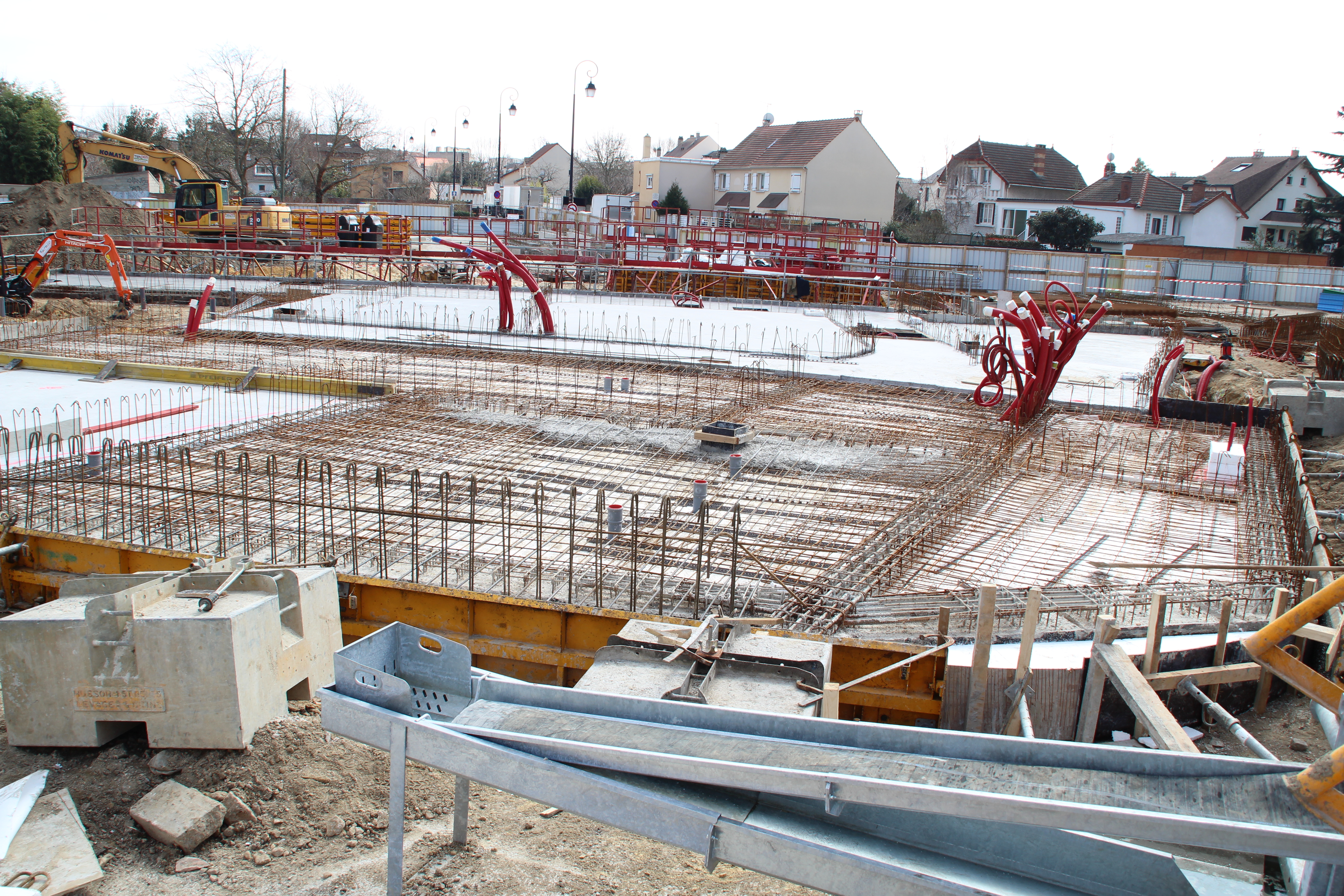
At the very hard end of the range sits vault construction, which the standard treats as its own category above the lettered walls. An open-storage vault may be a GSA-approved modular vault meeting Federal Specification FF-V-2737, or it may be site-built to one of two prescriptive recipes: reinforced concrete — walls, floor, and ceiling a minimum of eight inches thick, 2,500-psi concrete, 5/8-inch reinforcing rod centered in the pour on a six-inch grid horizontally and vertically, tied or welded at the intersections and anchored into the adjoining floor and ceiling to half their depth — or, where structure won’t permit a concrete vault, steel-lined construction using quarter-inch high-yield steel plate continuously welded to load-bearing members. Every vault is closed with a GSA-approved Class 5 or Class 8 vault door (a Class 6 door is acceptable within the United States). The vault is the shell taken to its logical extreme: when the material is the security, provenance becomes everything, because a rebar cage is the last place you can inspect before it disappears under concrete for the life of the building.
6.8 Inspectable space and co-utilization
Two related concepts govern how the finished shell relates to the world around it, and both are perimeter ideas rather than interior ones.
Inspectable space is the region surrounding and adjacent to the SCIF over which the organization exercises enough control to detect and evaluate a threat — the buffer within which an unauthorized transmitter or an intrusion attempt can be found. It matters to the shell in two ways. First, it sets the reference boundary for RF and TEMPEST performance: the Tech Spec ties RF protection to whether the SCIF provides adequate attenuation at the inspectable-space boundary, installed at the CTTA’s direction when the facility processes electronically and the surrounding space cannot be trusted to be clear of collection. A room surrounded by generous, controlled inspectable space needs less hardening than the identical room whose perimeter wall is shared with an uncontrolled public corridor, because in the first case an adversary cannot get a receiver close enough to matter. Second, it drives the treatment of shared and adjacent construction: where a SCIF perimeter abuts uncontrolled space directly — a party wall with a tenant next door, a slab shared with the floor below — the standard’s forced-entry and acoustic requirements are at their most demanding, precisely because there is no buffer absorbing the risk.
Co-utilization is the arrangement by which more than one organization shares an accredited SCIF, formalized through a memorandum of understanding or agreement and governed by the reciprocity principle that Volume 3 developed: the co-utilizing organization’s TEMPEST, telephone, and TSCM requirements are meant to be reciprocally accepted rather than re-litigated, and the storage arrangements are recorded in the FFC and the MOU. Co-utilization is an operational and accreditation matter more than a construction one, but it lands on the shell in the same place inspectable space does — at the perimeter, where the question of who controls the space on the other side of the wall determines how hard the wall has to work.
6.9 The shell is only as good as its holes
Stand back from the detail and the shell resolves into something conceptually clean: a six-sided continuous boundary — four walls of a standardized type, a true floor, a true ceiling — built to a documented design, from controlled materials, by (at the sensitive end) cleared labor under surveillance, and verified to contain speech to a specified Sound Group. That is the box. It is, on paper, nearly perfect: continuous, hardened, quiet, and inspected.
It is also, in reality, full of holes, every one of them deliberate. A SCIF that truly had no penetrations would be uninhabitable — no door to enter by, no air to breathe, no power for the equipment, no data path for the work, no plumbing for the coffee. Every one of those necessities is a controlled breach of the continuous perimeter, and every one is a place where the acoustic rating, the forced-entry rating, and the emanation posture can all leak at once. The Wall B and Wall C drawings hint at this even within their own frame — the fire-safe grout packed into every void above the track, the note that penetrations “shall be treated and sealed,” the surface-mounted (never recessed) outlets — because the spec’s authors knew that the wall field is the easy part. The hard engineering is at the openings.
That is the subject of Volume 7: the SCIF door and its GSA hardware, the HVAC and its acoustic baffles and Z-ducts, the plumbing and pipe penetrations, the conduit and cable entries, the ceiling grid and its sealing. The shell described here is the necessary foundation, but it is only a foundation. A perimeter is only as good as its holes — and a SCIF is a box designed entirely around the problem of putting holes in a box you were at great pains to make continuous.
Sources
- ODNI / National Counterintelligence and Security Center, IC Tech Spec for ICD/ICS 705 — Technical Specifications for Construction and Management of Sensitive Compartmented Information Facilities, Version 1.5.1 (26 July 2021). Chapter 2 (Risk Management / Security-in-Depth), Chapter 3 (Fixed Facility SCIF Construction — perimeter, Wall A/B/C, vaults, floors and ceilings, RF protection), and Chapter 9 (Acoustic Protection — Sound Groups, STC, NIC testing). Wall B and Wall C construction detail drawings reproduced from Chapter 3. Public copies: https://www.dni.gov/files/Governance/IC-Tech-Specs-for-Const-and-Mgmt-of-SCIFs-v15.pdf ; https://irp.fas.org/dni/icd/ics-705-ts.pdf ; U.S. Navy EXWC mirror (v1.5.1): https://exwc.navfac.navy.mil/Portals/88/Documents/EXWC/DoD_Locks/PDFs/ICD-ICS-705_Tech_Spec.pdf ; construction figures rendered from the teotech.com hosted PDF: https://teotech.com/wp-content/uploads/2018/03/icd-ics-705-tech-spec.pdf
- Intelligence Community Standard (ICS) 705-1, Physical and Technical Security Standards for Sensitive Compartmented Information Facilities (17 September 2010) — AO/SSM/CST roles restated in Tech Spec Chapter 3. https://exwc.navfac.navy.mil/Portals/88/Documents/EXWC/DoD_Locks/PDFs/ICS-705-1.pdf
- Federal Specification FF-V-2737 (modular vaults); FF-L-2740A and FF-L-2890 (high-security combination locks and pedestrian deadbolts); GSA vault-door classes — as referenced in Tech Spec Chapter 3 and Chapter 8. GSA Global Supply / federal specifications index: https://www.gsaelibrary.gsa.gov/
- On the lettered wall types and their forced-entry vs. acoustic logic: Strategic Solutions Unlimited, “An Overview of ICD 705 Perimeter Wall Requirements,” https://strategicsolutionsunlimited.com/an-overview-of-icd-705-perimeter-wall-requirements/ ; SPG Secure, “ICD 705 Tech Spec Requirements for Type A, B, or C Wall,” https://www.spgsecure.com/post/icd705-tech-spec-requirements-for-type-a-b-or-c-wall ; Cooper Builds, “SCIF/SAPF Wall Types: Understanding ICD 705 Minimum Requirements and Applications,” https://www.cooperbuilds.com/post/scif-sapf-wall-types-understanding-icd-705-minimum-requirements-and-applications
- On acoustic Sound Groups, STC/NIC, and when acoustic testing is required: SPG Secure, “STC — Deciphering ICD 705 Acoustic Requirements,” https://www.spgsecure.com/post/stc-deciphering-icd-705-acoustic-requirements-and-when-testing-is-required-part-i ; ASTM E413 (STC classification) and ASTM E90 (laboratory transmission loss).
- On expanded metal as a construction and penetration-resistance material: “Expanded metal,” Wikipedia, https://en.wikipedia.org/wiki/Expanded_metal
- On the Moscow embassy construction-compromise history informing controlled-construction doctrine: “Sensitive compartmented information facility,” Wikipedia, https://en.wikipedia.org/wiki/Sensitive_compartmented_information_facility (and Volume 2 of this deep dive).
- Figure image sources are recorded with per-file provenance and license in
photo_credits.v6.txt.
Comments (0)