Scif · Volume 7
Anatomy and Construction II: Doors, Ducts, and Every Other Hole
7.1 The shell is only as good as its holes
Volume 6 stood up the box: a true-floor-to-true-ceiling perimeter of studs, gypsum, expanded metal, and acoustic batt, sealed into a continuous acoustic and (where required) electromagnetic boundary. If a SCIF were a solid casting with no way in and no services crossing its skin, the engineering would more or less end there. It is not. People have to get in and out. Air has to move through it or the occupants suffocate. Power, data, water, and fire-protection piping have to cross the line. Every one of those necessities is a deliberate hole punched in the boundary that Volume 6 worked so hard to make continuous, and every hole is a place where the acoustic seal, the intrusion resistance, and the RF integrity can leak back out. A perimeter is exactly as good as its worst penetration, which is why the penetrations — not the walls — are where SCIF engineering gets genuinely interesting.
The IC Tech Spec for ICD/ICS 705 treats this as a first-class problem. Its Fixed Facility SCIF Construction chapter devotes explicit criteria to doors, windows, vents, ducts, and pipe and conduit penetrations, and its acoustic chapter returns to the same openings from the transmission-loss side. The governing instinct throughout is minimization: keep penetrations to a minimum, and treat the ones you cannot avoid so thoroughly that they perform like the wall they interrupt. The boundary is taken here hole by hole — the door and its lock first, because that is the one penetration a human uses every day and the one an adversary attacks first, then the ducts, the pipes, the RF vents, the rare window, and finally the discipline that keeps the whole leaky inventory documented and inspectable.
7.2 The door: the biggest hole you build on purpose
Every other penetration is sized to a service — a duct to a CFM, a conduit to a wire count. The door is sized to a human being, which makes it, by a wide margin, the largest single opening in the perimeter. Worse, it is an opening designed to be opened. A wall gets to be a monolithic assembly; a door is a moving leaf, a frame, a gap around all four edges, a set of hinges, a latch, and whatever hardware lets it swing, close, seal, and lock. Each of those is a discontinuity, and the sum of them is why the door is almost always the acoustic weak point of a SCIF and the first thing a forced-entry attempt goes after.
The Tech Spec resolves the door into a small number of approved answers. The primary SCIF entrance — the one door where visitor control is conducted — carries the heaviest requirements, and the standard is emphatic that there shall be only one such primary entrance. Where the required protection is high, that entrance is built as a vault: a GSA-approved vault door set in a hardened frame. GSA vault doors are governed by Federal Specification AA-D-600, and the class that dominates SCIF and secure-storage practice is Class 5. A Class 5 vault door (the “5-V” vault variant) is rated to resist 20 man-hours of surreptitious entry, 30 man-minutes of covert entry, and 10 man-minutes of forced entry — three separate attack models, because a lock that laughs off a safecracker’s stethoscope is not automatically hard to pry. The family has siblings: the Class 5-A armory door and the Class 5-B ballistic door share the forced- and covert-entry ratings while trading away or adding capability (the 5-B adds ballistic resistance), and a heavier Class 6 exists above them. There is, contrary to a common misremembering, no “Class 8” vault door; the container-and-door class ladder tops out at 5 and 6 for current GSA approvals, with the old Classes 1 through 4 long obsolete and off the Federal Supply Schedule. The number that matters for an engineer is 10 man-minutes of forced entry, because that figure is precisely what the intrusion-detection system’s response time has to beat — the door buys minutes, the alarm and the guard force spend them.

Not every SCIF door is a vault door. A great many SCIFs are accredited with a standard personnel door — a heavy hollow-metal or acoustic-rated leaf in a welded steel frame — provided the walls, alarms, and access control carry the risk that a lighter door sheds. The distinction between open storage and closed storage drives the choice: a SCIF approved for open storage of classified material (left out on desks and in unlocked cabinets after hours) leans harder on the perimeter, including the door, than one where everything goes into GSA containers at close of business. Either way, the Tech Spec requires that SCIF doors and their frame assemblies meet the acoustic requirements of the facility’s Sound Group — STC 45 for normal speech, STC 50 where audio is amplified — and that is a tall order for a moving object.
7.2.1 Why the door leaks sound, and what fights back
A wall achieves STC 50 by being a heavy, sealed, multi-layer assembly with no through-air path. A door has a through-air path around its entire perimeter by definition, and air-paths are acoustic short circuits: a gap that passes a whisker of light passes a great deal of sound. Closing those gaps is the entire art of the acoustic door. The leaf itself is made heavy and internally damped — a steel skin over a mineral or honeycomb core, sometimes a full acoustic assembly rated to STC 50 or better on its own. The perimeter gap is closed with compression sound seals or magnetic gasketing at the head and jambs, so that when the door is latched the leaf squeezes into a continuous elastomeric line of contact. The bottom — the hardest edge, because it has to clear the floor to swing — gets an automatic door bottom, a spring-loaded drop seal that retracts as the door opens and drops onto the threshold as it closes, or a compression astragal and sweep. Where a pair of doors meet, a meeting-stile astragal seals the vertical gap between the two leaves. Every one of these is a wear item, and every one is a place where an out-of-adjustment seal quietly drops the whole assembly below its rated STC. The acoustic door is the perimeter component most dependent on maintenance, which is why acoustic testing after installation (and the SSM’s periodic checks) matters more here than anywhere else on the boundary.
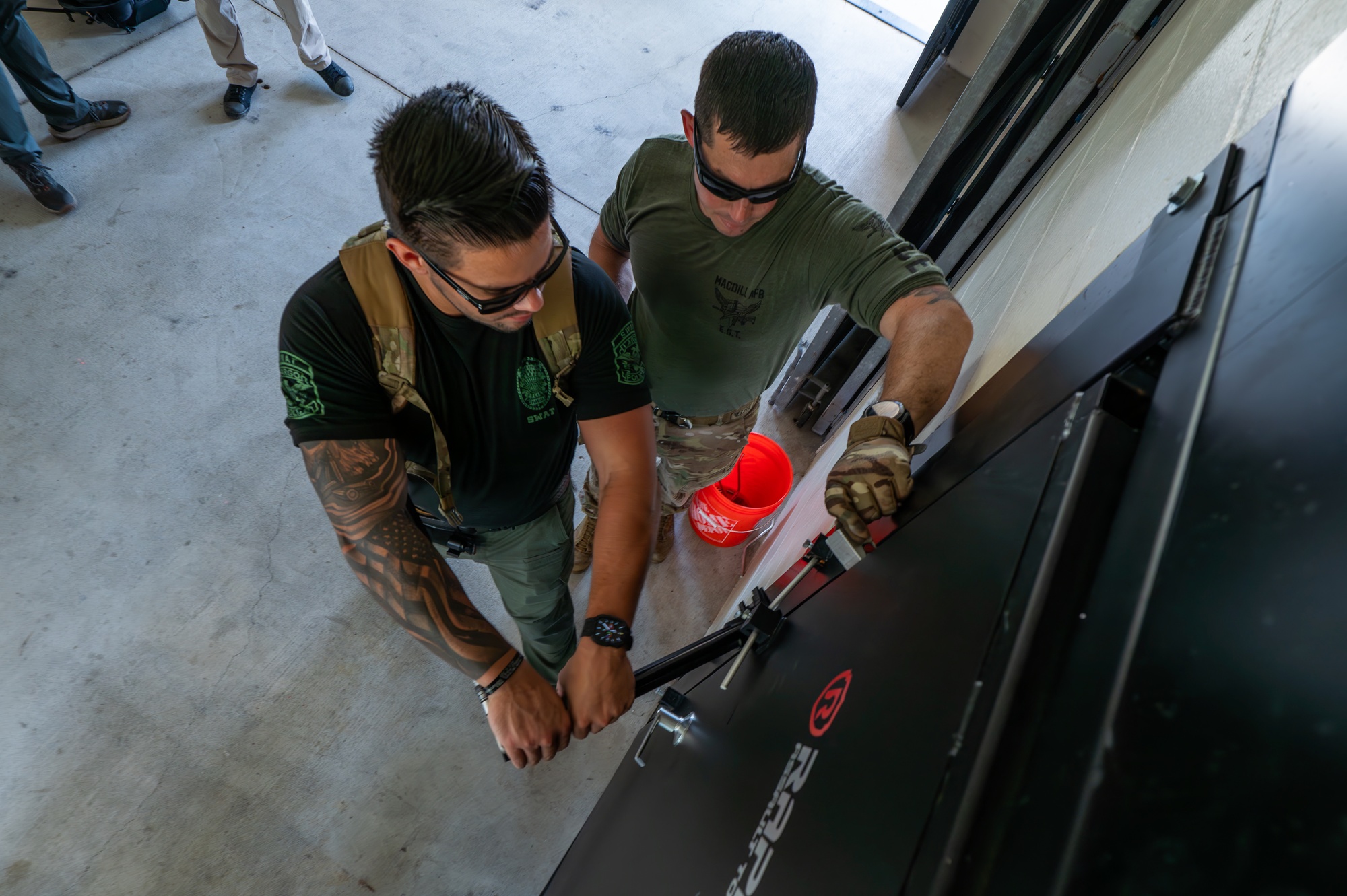
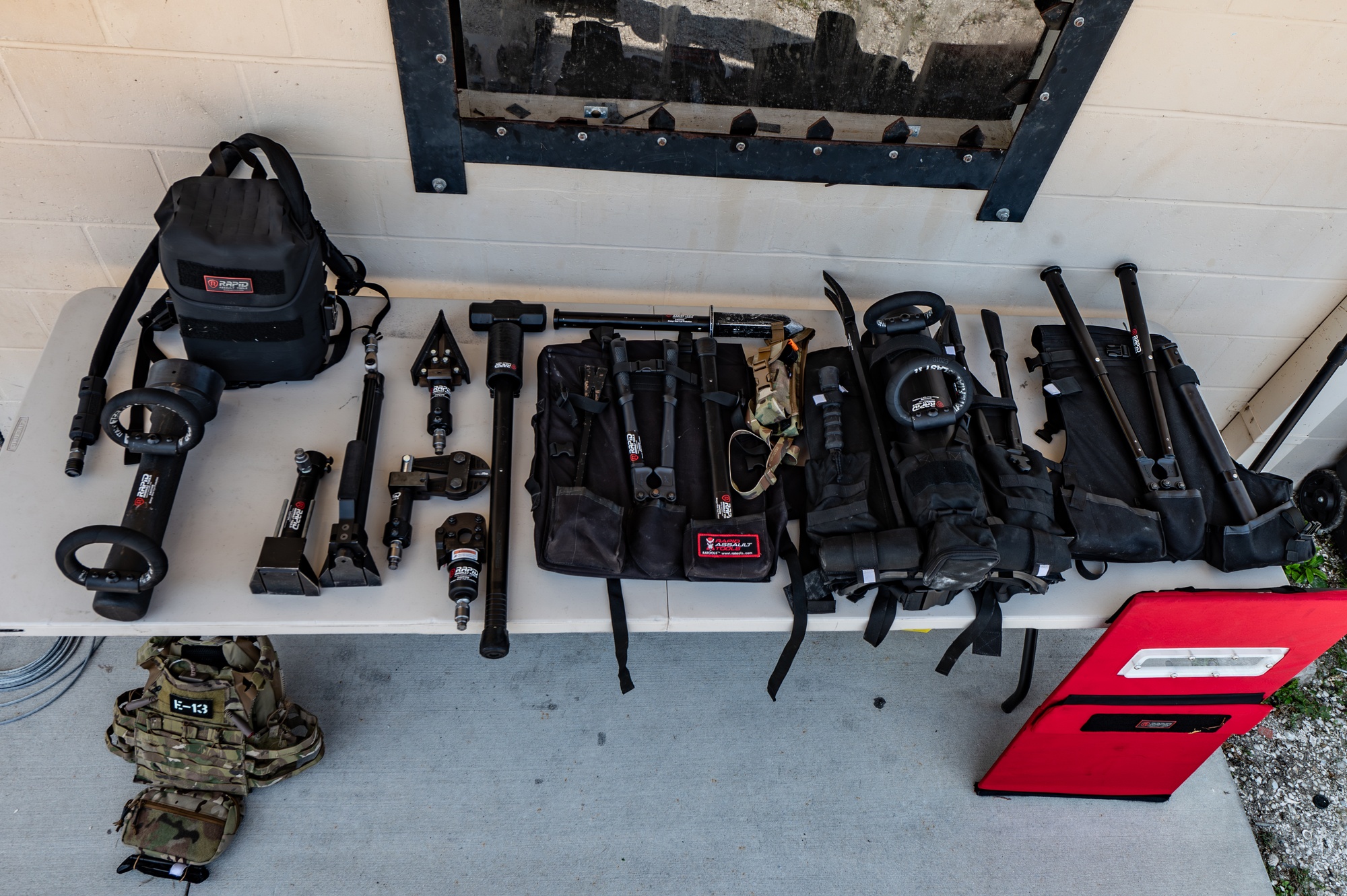
Hinges and closers add their own considerations. A heavy door wants heavy-duty or continuous geared hinges to carry the leaf without sagging — a sagging door breaks its own bottom seal. Hinge pins on an out-swing door are an attack surface (pull the pins, lift the leaf), so security hinges use non-removable or set-screw pins, or the door swings in. The MacDill breaching project that produced Figure A built a dedicated hinge puller into its SCIF-door kit precisely because the hinge line is the door’s mechanical Achilles’ heel. An automatic door closer ensures the door actually returns to the latched, sealed position rather than being left ajar — an unlatched acoustic door is acoustically just an expensive hole — and the interplay between the closer and any authorized hold-open is a genuine tension. Doors may be held open during working hours for airflow and traffic, but a held-open SCIF door defeats both the acoustic seal and the access control, so hold-opens are procedural, supervised, and released (often automatically, on alarm or at end of day) rather than a permanent fixture. Fire code complicates all of this: the same door that security wants deadlocked from outside must, by NFPA and local code, open freely from the inside in an emergency. The negotiated truce is deadlocking panic hardware — a crash bar that always releases the latch from within, no exterior trim or keyway, alarmed, and acoustically matched to the adjacent wall — on the emergency-exit doors, while the primary entrance carries the access control and the vault-grade lock.
7.2.2 The day gate
A recurring and underappreciated fixture is the day gate: a lightweight, often grille-type inner gate mounted just inside the primary vault door. During working hours the heavy vault door stands open (held back against its rated forced-entry job, which only matters when it is closed and locked), and the day gate does the daytime work — it lets air and sightlines through, keeps casual foot traffic controlled, and gives the occupants a lockable barrier without cycling the multi-hundred-pound vault door every time someone steps out. The vault door and its FF-L-2740 lock are the after-hours barrier; the day gate is the duty-hours one. This split — a heavy secure barrier for when the space is unoccupied and unwatched, and a light convenience barrier for when it is staffed — is a theme that repeats in the lock architecture below.
7.3 Locks: two philosophies on one door
The most important thing to understand about a SCIF door’s locks is that there are usually two independent locking systems on it, doing two different jobs, and conflating them is the most common misconception in the whole subject.
The first is the Access Control System (ACS) — the day-to-day lock. This is the electronic reader, the PIN pad, the badge or biometric, the electric strike or magnetic lock that lets cleared people in and out during operations and logs who did so. The ACS is a convenience-and-accountability device: it controls access while the SCIF is occupied and operating. It is emphatically not the barrier that protects the space after hours, and the standard is careful to keep the two separate.
The second is the GSA-approved combination lock — the after-hours secure lock. When the last person leaves and the SCIF is secured, the space is protected not by the badge reader but by a high-security combination lock meeting Federal Specification FF-L-2740, thrown on the vault door or the GSA container, and by the intrusion-detection system. FF-L-2740 is the U.S. Government’s top specification for electromechanical combination locks, and for three decades it has been met by essentially one product family: the Kaba Mas X-0 series (now dormakaba). The lineage is worth knowing because it appears on drawings and inventories constantly: the X-07 was approved in February 1992 as the first lock ever to meet FF-L-2740; the X-08 followed in March 1999; the X-09 in June 2002; and the current X-10, meeting FF-L-2740 revision B, in April 2013. They are electromechanical but self-powered — the act of turning the dial spins a small generator (dormakaba’s “PowerStar” technology), so there is no battery to die and no external power to cut. That last property is the point: the secure lock cannot be defeated by pulling the building’s power, because it makes its own. A companion door-mounted variant, the CDX series, provides the same lock as a pedestrian-door deadbolt, and a single change key works across the whole X-07/08/09/10 family.
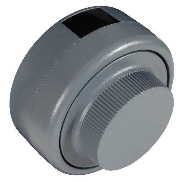
The reason for the two-lock architecture is the same reason the vault door has a day gate: the threat model changes when the room empties. While occupied, the space is watched, and the job is to control and account for who enters — the ACS’s job, and it can be electronic and networked because it is backstopped by human presence. While unoccupied, there is no one watching, so the space must rely on a barrier that needs no power, no network, and no monitoring to hold — the mechanical/electromechanical GSA lock, backstopped by the IDS. An electronic ACS lock, however sophisticated, is the wrong tool for the after-hours job precisely because it depends on the very infrastructure (power, network) an adversary would attack first; the GSA lock depends on nothing but its own boltwork and the turning of its dial.
Around both locks sits key and combination control, which is administrative but load-bearing. Combinations to GSA locks are treated as classified to the level of the material they protect, are changed on a schedule and whenever a cleared person with knowledge of them departs, and are recorded on the appropriate form and stored in another GSA container — a small recursion that quietly implies every SCIF needs a second lock to protect the record of its first. The SSM owns this discipline, and it is exactly the sort of unglamorous control whose failure has historically undone otherwise excellent physical security.
7.4 HVAC and ductwork: the signature SCIF penetration
If the door is the penetration an adversary attacks, the HVAC duct is the penetration an engineer obsesses over, because it is a large, continuous, metallic tube that has to move real volumes of air across the acoustic and electromagnetic boundary — a triple threat rolled into one hole. A duct is simultaneously a man-passage opportunity (if it is big enough to crawl through), an acoustic pipe (it will happily conduct intelligible speech straight out of the SCIF), and, in a shielded facility, a waveguide that will carry RF right through the Faraday boundary. The Tech Spec’s treatment of ducts is correspondingly the most detailed penetration criteria in the document, and it attacks all three problems at once.
The governing dimension is 96 square inches. Any vent or duct opening that penetrates the SCIF perimeter and exceeds 96 square inches in cross-sectional area must be protected against man passage — unless one dimension of the opening is six inches or less, in which case a human cannot fit through it and bars are not required. Where bars are required, the standard is specific: half-inch steel man-bars, spaced and welded at six inches on center, turning the duct into a grille no person can pass. This is the physical-security layer, and it is why a large SCIF return-air duct, cut open, reveals a welded steel cage rather than an open pipe. (The same 96-square-inch / six-inch logic governs any large opening in the perimeter, not just ducts.)
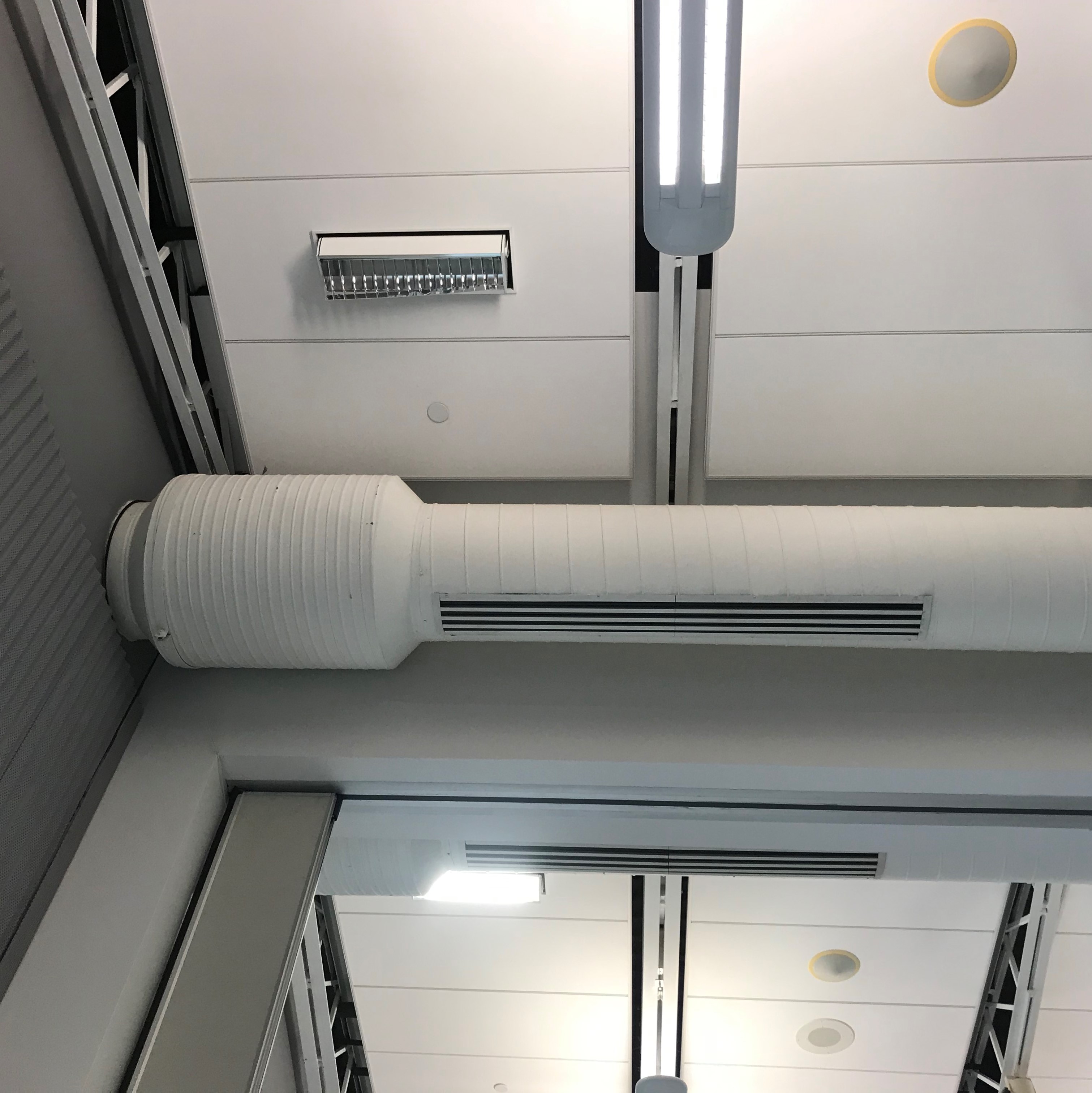
But man-bars do nothing for sound. Acoustically, an open duct is a disaster: it bypasses the STC-50 wall entirely, offering speech a clear sheet-metal path to the outside. The standard’s answer is a sound baffle — and the canonical implementation is the Z-duct (or S-duct), an acoustically lined transfer duct bent through a Z- or S-shaped path so that sound has to reflect off absorptive-lined surfaces several times before it can traverse the penetration. The geometry is not arbitrary: the Tech Spec’s own figure specifies leg lengths on the order of three times the duct dimension (“3x”) so that the bends are gradual enough to pass air with acceptable pressure drop while forcing the sound to bounce through lined turns that eat its energy. Each reflection off the acoustic lining converts acoustic energy to heat; a duct with no straight line-of-sight through it and several lined bends can add tens of dB of transmission loss, enough to bring the duct’s performance back up to the wall’s. Larger installations use a purpose-built duct silencer or sound attenuator — a lined, often circular or splitter-type in-line device that does the same job with engineered absorptive baffles (Figure E). The Tech Spec also permits permanently installed metal sound baffles or “wave forms” set at the required spacing to satisfy the man-passage requirement and the acoustic requirement together, which is elegant: the same lined baffles that scatter the sound are close-spaced enough that no one crawls past them.
The third layer applies only to shielded SCIFs: RF treatment. A metallic duct penetrating a Faraday boundary is a waveguide, and an untreated one will pipe emanations straight through the shield — the whole subject of Volume 8. The countermeasure lives at the shield wall, where the duct passes through a honeycomb waveguide vent (below) or a bonded transition rather than an open hole, so the air gets through and the RF does not. The important structural point for this volume is that a SCIF duct is not one problem solved once; it is three problems solved in series — man-bars for the burglar, baffles for the eavesdropper’s ear, and honeycomb or bonded transitions for the eavesdropper’s antenna — and a compliant duct penetration carries all three treatments stacked on the same opening.
7.5 Vents and RF air handling: the honeycomb waveguide
Where a shielded SCIF needs to move air through the RF boundary without a full ducted transfer, it uses a honeycomb waveguide air vent — one of the more satisfying pieces of physics in the whole facility. The device is a panel packed with a dense honeycomb of small metallic cells, brass or steel, each cell a short tube. Air flows through the open cells with only modest pressure drop, but each cell behaves as a waveguide below cutoff: a hollow metallic tube passes electromagnetic energy only above a cutoff frequency set by its cross-section, and below that frequency the field is evanescent and attenuates exponentially along the tube’s length. Make the cells small (cutoff up in the tens of GHz) and the tube reasonably deep (the honeycomb’s roughly 4:1 depth-to-opening ratio), and every frequency of practical concern falls far below cutoff and is attenuated by an enormous margin over the panel’s depth — routinely 80 to 100+ dB of shielding effectiveness — while the air sails through. It is the same principle that lets the metal mesh over a microwave oven’s window pass visible light (wavelength far above the mesh’s cutoff) while trapping the 2.45 GHz cooking field (far below it), scaled and stacked for a ventilation opening.
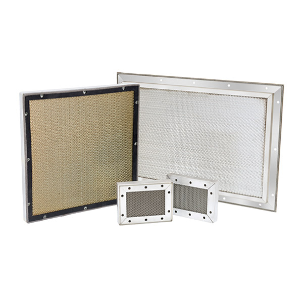
The engineering subtleties are all at the edges. The honeycomb panel is only as good as its bond to the shield: an EMI gasket runs the full perimeter of the frame so the panel is electrically continuous with the enclosure wall, because a gap around the frame is a slot antenna that undoes the honeycomb’s work. The cells must be fused, not merely stacked — vendors solder-fuse or braze the honeycomb into a solid conductive matrix, since an unbonded seam between cells is another leak. Steel honeycomb gives better low-frequency magnetic shielding; brass is chosen for non-ferrous or high-humidity requirements. Honeycomb vents are introduced here as the RF layer of the air-handling story; Volume 8 takes up shielding effectiveness in earnest and Volume 9 returns to honeycomb and waveguide-below-cutoff as the general solution for getting anything — air, light, a fiber — through a shielded boundary without carrying a signal.
7.6 Plumbing and pipe penetrations
Pipes and conduit cross the perimeter for the same mundane reasons pipes cross any wall: water supply and drainage, fire-protection sprinkler mains, and the electrical conduit that Volume 9 will worry about at length. Each is a smaller hole than a duct but subject to the same instinct — minimize them, and treat the ones you keep. The Tech Spec’s perimeter-penetration criteria require that all penetrations be kept to a minimum, that the wall around each be finished to eliminate any opening between the pipe and the wall, and that the void be sealed all around with acoustic material (and, where fire-rated, fire-safe non-shrink grout or an approved firestop) so the penetration performs acoustically like the wall it interrupts. A pipe passing through an unsealed sleeve is an acoustic and, potentially, an RF leak; the seal is what makes it a pipe through a wall rather than a hole with a pipe in it.
Two refinements matter for an EE reader. First, metallic penetrations may require TEMPEST countermeasures — a metal pipe or conduit that runs from inside a shielded SCIF to the outside is a conductor bridging the RED and BLACK sides, a ready-made path for conducted emanations, so where the CTTA requires it the pipe gets a dielectric (non-conductive) break or union to interrupt the metallic path, and the shield is maintained by a bonded penetration rather than a continuous conductor. This is the plumbing equivalent of the honeycomb vent: let the water through, stop the current. Second, the standard anticipates future work: it permits installing spare conduit for future utility expansion, provided the spare is filled with acoustic fill and capped so an empty future conduit does not sit in the wall as a pre-drilled acoustic and RF hole waiting to be exploited. An unfilled spare conduit is one of those quiet deviations a good inspection catches.
7.7 Windows: the penetration you try not to have
The cleanest window, from a SCIF engineer’s standpoint, is the one that was never installed. Windows are simultaneously a visual, an acoustic, and an RF weakness, and the Tech Spec’s posture is avoidance: keep them out of the SCIF perimeter where possible. Where a window is unavoidable, it must provide visual, acoustic, and (where required) RF protection, and it must not offer a line of sight into the SCIF from any uncontrolled vantage. Ground-floor and otherwise accessible windows draw the strictest treatment because they are also a forced-entry path; the standard’s instinct there is to eliminate the opening or harden it to the wall’s standard.
The treatments stack the same way the duct’s do. Visual: the window is made opaque or its sightline is blocked — an inside partition, opaque film, blinds that are kept closed as a procedural matter, or simply obscured glazing, because the eavesdropper who can read the whiteboard through the glass has defeated the facility without any electronics at all. Acoustic: the glazing is upgraded to a heavy multi-pane assembly whose STC approaches the wall’s, since ordinary glass is acoustically transparent by comparison, and the frame is sealed like any other penetration. RF: where shielding is required, the glass carries a transparent conductive coating or an embedded fine wire mesh bonded to the shield, the optical analogue of the honeycomb vent — pass the light, stop the field. Forced entry: security glazing, laminates, or bars bring the opening up toward the wall’s intrusion resistance. A window that has been through all four treatments is an expensive, heavy, opaque, sealed, shielded assembly that no longer does the one thing windows are for — which is exactly why the standard would rather the designer not have one.
7.8 Acoustic sealing everywhere, and the flanking-path problem
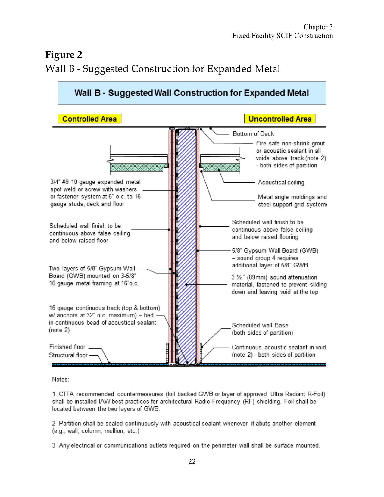
Underneath the door, the duct, the pipe, and the window sits a single unglamorous discipline that determines whether any of them actually work: continuous acoustic sealing at every joint. Sound, like water, does not care about the wall’s rated performance; it finds the unsealed gap and pours through it. A perimeter of STC-50 assemblies stitched together with unsealed seams performs like its seams, not its assemblies. The Tech Spec’s Wall B figure (Figure D) makes the rule explicit in its notes: the partition shall be sealed continuously with acoustical sealant wherever it abuts another element — wall, column, mullion, deck, floor — in continuous beads, both sides. Every place two things meet is a joint, and every joint gets caulked.
The subtler failure is the flanking path: sound that goes around the barrier rather than through it. A wall can be perfect and still leak if speech couples into the floor slab, the deck above a suspended ceiling, a shared plenum, or a run of conduit, and re-radiates on the far side — the reason Volume 6 insisted the perimeter run true-floor-to-true-deck and the reason the deck and slab get treated too. Penetrations are prime flanking paths: a back-to-back pair of electrical outlets in the perimeter wall, boxes cut into the gypsum only a stud bay apart, is a classic short circuit — the two boxes very nearly connect the two faces of the wall through a thin diaphragm of nothing. The countermeasures are equally specific. The Tech Spec (Figure D, Note 3) requires that electrical and communications outlets on the perimeter wall be surface mounted rather than recessed, so the wall’s mass is never cut through for a box in the first place; where boxes must be recessed, good practice offsets them so no two are in the same stud cavity and pads or boots the box to restore the wall’s continuity. Every device that would otherwise be sunk into the perimeter — outlets, switches, panels, back-boxes — is treated as a miniature penetration and sealed, offset, or surface-mounted accordingly. The flanking-path problem is why an acoustic consultant walks a finished SCIF running a loudspeaker inside and a meter outside, hunting for the one unsealed joint or back-to-back box that is quietly broadcasting.
7.9 The penetration schedule and inspection discipline
All of this — every door, gate, duct, silencer, honeycomb vent, pipe, conduit, spare sleeve, window, and back-box — is only as trustworthy as the record that tracks it. The organizing artifact is the penetration schedule: a documented inventory of everything that crosses the SCIF perimeter, what it is, where it is, and how it is treated (man-bars, baffle, dielectric break, seal, cap). The schedule is not bureaucratic ornament; it is what makes the perimeter inspectable. A boundary you cannot enumerate is a boundary you cannot certify, and the whole accreditation model rests on being able to walk the perimeter against a list and confirm that each hole is treated as designed.
The discipline runs through the facility’s life. During construction — when the SCIF is a stud skeleton with its penetrations exposed and is at its most vulnerable to a hostile implant slipped into a wall or a duct — the Construction Security Plan governs who has access and how materials are controlled, and periodic security inspections by the SSM or designee verify the work as it is buried, because a penetration is far cheaper to inspect before the drywall closes over it than after. At accreditation, the completed penetration treatments feed the Fixed Facility Checklist and any TEMPEST addendum the AO reviews. And across the operational life, the SSM re-inspects: seals age, drop-bottoms fall out of adjustment, a maintenance crew cuts a new conduit and forgets to seal it, a spare sleeve loses its cap. The penetration schedule is the map that turns each of those from an invisible latent leak into a checklist line item someone is accountable for. The forced-entry rating of the door and the shielding effectiveness of the honeycomb vent are engineering facts; the penetration schedule is what keeps them true a decade after the ribbon-cutting.
7.10 Where this leads
The perimeter is now fully accounted for: Volume 6 built the continuous shell, and this volume treated every hole in it — the door and its two-philosophy lock stack, the triple-treated duct, the honeycomb-vented and dielectrically-broken services, the reluctant window, and the sealing-and-schedule discipline that keeps the whole leaky-by-necessity inventory honest. Two threads deliberately ran up against a boundary of their own here and got handed forward. The RF layer — waveguide-below-cutoff, honeycomb vents, dielectric breaks, the bonded penetration — was introduced as the third treatment on ducts and pipes but not derived; Volume 8 takes up emanation security and shielding effectiveness as its own subject, and explains what “80 to 100 dB” actually buys. And the harder version of the same question — how to get working power and live data through a shielded boundary without the conductor itself carrying the signal out — is Volume 9: power-line filters, fiber versus copper, protected distribution systems, grounding, and the filtered penetrations that make a shielded SCIF a usable room rather than a sealed tomb. The door lets people through; the next two volumes are about letting the electrons through on exactly the same terms — in, but never carrying anything back out.
Sources
- ODNI / National Counterintelligence and Security Center, IC Tech Spec for ICD/ICS 705 — Technical Specifications for Construction and Management of Sensitive Compartmented Information Facilities, Version 1.5.1 (26 July 2021), Chapter on Fixed Facility SCIF Construction (SCIF Perimeter Penetrations Criteria: doors, windows, vents and ducts, pipe/conduit penetrations, the 96-square-inch man-bar rule, Figure 4 “Typical Perimeter Air (Z) Duct Penetration”) and the Acoustic Protection chapter (Sound Groups / STC, door acoustic requirements). Figure 2 “Wall B – Suggested Construction for Expanded Metal” reproduced from this edition. https://www.dni.gov/files/NCSC/documents/Regulations/IC_Technical_Specifications_for_Construction_and_Management_of_Sensitive_Compartmented_Information_Facilities_v151_PDF.pdf ; v1.0 (5 May 2011) figure mirror: https://teotech.com/wp-content/uploads/2018/03/icd-ics-705-tech-spec.pdf
- Federal Specification AA-D-600, Door, Vault, Security — GSA-approved vault door classes (Class 5-V / 5-A / 5-B; Class 6) and their surreptitious / covert / forced-entry man-hour and man-minute ratings. Vendor summaries: International Vault, “GSA Standards,” https://internationalvault.com/gsa-standards/ ; “Class 5 / 5-A / 5-B Vault Doors,” Safe & Vault, https://www.safeandvault.com/faq/116-vaults-a-doors/701-class-5-a-b
- Federal Specification FF-L-2740 (rev. B), Locks, Combination — the high-security electromechanical lock spec, and the Kaba Mas / dormakaba X-07 (1992), X-08 (1999), X-09 (2002), X-10 (2013) lineage and self-powered (“PowerStar”) design; CDX pedestrian-door variants. dormakaba / Kaba Mas: https://www.kabamas.com/x-10-high-security-lock/ and DoD Lock Program resources https://www.kabamas.com/product-resources/department-of-defense-lock-program/ ; X-10 product data via GoKeyless https://www.gokeyless.com/products/kaba-mas-x10-combination-lock
- U.S. Navy NAVFAC EXWC / DoD Lock Program, GSA-Approved Vault Doors and Security Containers — Class 5 vault doors and Class 5/6 security containers for classified storage. https://exwc.navfac.navy.mil/DoD-Lock-Program/Security-Hardware/GSA-Approved-Vault-Doors/
- On honeycomb waveguide-below-cutoff air vents and shielding effectiveness: MAJR Products, “Honeycomb Waveguide Panels for EMI/RFI Shielding (ICS/ICD 705),” https://www.majr.com/product/honeycomb-waveguide-panels/ ; ETS-Lindgren, “EMI/RFI Shielded Waveguide Air Vents,” https://www.ets-lindgren.com/product/emi-rfi-shielded-waveguide-air-vents/ ; RF Essentials, “What is the honeycomb waveguide vent…,” https://rfessentials.com/rf-knowledge-base/what-is-the-honeycomb-waveguide-vent-and-how-does-it-provide-both-airflow-and-sh/
- On acoustic door assemblies (leaf, perimeter and drop-bottom seals, astragals, thresholds, STC ratings): Krieger Specialty Products acoustical doors, https://www.kriegerproducts.com/acoustical/ ; AMBICO acoustic steel doors, https://www.ambico.com/acoustic-steel-doors-frames/ ; NGP STC-rated door seal charts, https://www.ngp.com/plugins/NGPAdmin/data/products/STC_Charts1.pdf
- On the SCIF door as a forced-entry problem and the purpose-built breaching kit / hinge puller: “6th SFS makes a breakthrough in Breaching Technology,” DVIDS, 16 May 2024 (U.S. Air Force photos by Senior Airman Michael Killian), https://www.dvidshub.net/news/472038/6th-sfs-makes-breakthrough-breaching-technology and image https://www.dvidshub.net/image/8424318/
- On GSA SCIF door / lock hardware practice, day gates, and the ACS-vs-GSA-lock separation: A to Z Lock & Safe, “GSA Guidelines for SCIF Doors & Security Containers,” https://www.atozlockandsafe.com/gsa-guidelines-for-scif-doors-security-containers/
Comments (0)