Capacitors · Volume 1
What a Capacitor Is
1.1 The One-Sentence Answer, and Then the Real One
A capacitor is a device that stores energy in an electric field established between two conductors that are separated by an insulator. That is the sentence to carry away if only one sentence survives. Everything else in this volume — and, arguably, in the thirteen that follow — is an unpacking of it: what “stores energy in an electric field” actually means, why the two conductors have to be kept apart, why the insulator between them turns out to be the interesting part, and why a component whose entire job is not to conduct is nonetheless the most numerous part in almost every piece of electronics ever built.
The everyday physical reality is even simpler than the sentence. Take two flat pieces of metal — call them plates — hold them close together but not touching, and put a thin sheet of insulating material between them so they cannot short out. That is a capacitor. Connect the two plates to the two terminals of a battery, and something quietly remarkable happens: electrons pile up on the plate connected to the negative terminal and are pulled away from the plate connected to the positive terminal, until the plates hold equal and opposite charges. No current ever crosses the gap — the insulator forbids it — yet the battery has pushed charge onto the device, and that charge stays put even after the battery is disconnected. The capacitor has remembered the battery. That memory, held in the invisible field spanning the gap, is the whole trick.
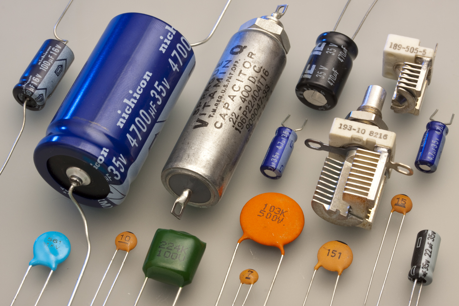
The photograph above is a fair warning about how much variety hides behind that one simple idea. The fat aluminium cans, the little disc with two legs, the boxed plastic block, the blue teardrop — these are all capacitors, and they range in value and physical size across more than twelve orders of magnitude. A designer picks between them for reasons this series exists to explain. But every one of them is, at heart, two conductors and an insulator, and every one of them obeys the same handful of equations introduced below. Get those equations into the bones and the rest of the field becomes a story of engineering compromises rather than a bag of unrelated parts.
A note on an old word. For most of the twentieth century a capacitor was called a condenser, and the term survives in a few corners — the “condenser” in a points-and-condenser ignition system, the “condenser microphone,” the tuning “condenser” in an antique radio. It means exactly the same thing. The word “capacitor” won out because it points at the quantity that actually matters, capacitance, rather than at a misleading mental picture of charge being condensed like steam. Where a vintage schematic says condenser, the reader should simply read capacitor.
1.2 The Water Analogy, Done Honestly
Electricity is invisible, so engineers reach for water. The analogy is genuinely useful here, provided one uses the right water picture and is honest about where it fails. The wrong picture — a capacitor as an open bucket that fills up — quietly implies that current flows into the device and stays there, which is not what happens, because current never crosses the insulating gap. The right picture is a sealed tank divided down the middle by a stretchy rubber membrane.
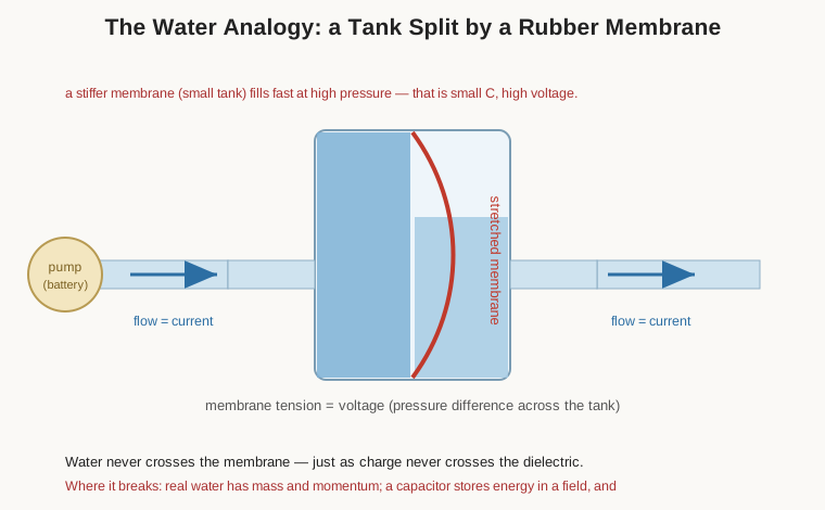
In this picture the moving water is electric current, and the pressure difference across the tank is voltage. When the pump — the battery — pushes water into the left side, the membrane stretches and bulges to the right, shoving an equal volume of water out of the right side. To an observer watching only the pipes, water flowed straight through the tank; in reality no single water molecule crossed the membrane. This is exactly how a capacitor behaves. Electrons crowd onto one plate and an equal number are repelled off the other, so current appears to “flow through” the capacitor even though the dielectric is a perfect wall. The more the membrane stretches, the harder it pushes back, and eventually its tension balances the pump’s pressure and the flow stops. The tank is now “charged”: storing energy purely in the strained rubber, with no water having gone anywhere it could not come back from.
The analogy pays several dividends immediately. A stiffer membrane bulges less for a given push, so it reaches balance quickly and holds little water at high pressure — that is a small capacitance rated for high voltage. A large, floppy membrane accepts a lot of water before it pushes back — large capacitance, and typically a modest voltage rating. Disconnect the pump and the stretched membrane stays stretched, holding its energy indefinitely; reconnect a path and it snaps back, driving a surge of return flow. Every one of those behaviours has an exact electrical counterpart, and they are worth holding onto.
Where does the analogy break? In two places worth naming. First, real water has mass and momentum, so a water tank has an inertia that a capacitor’s field does not; the electrical analogue of inertia is inductance, which is a different component entirely (and the next dive in this passive-components program). Second, and more subtly, the analogy hides where the energy actually lives. It is tempting to say the energy is “in the membrane,” and that is a fine picture, but the electrical truth is stranger and more important: a capacitor’s energy is stored in the electric field in the empty space and dielectric between the plates, not in the plates and not in the charges themselves. That distinction seems academic until one is standing in front of a charged high-voltage capacitor, at which point it becomes the difference between respect and a trip to the emergency room. Hold that thought; it returns under “energy.”
1.3 Charge and Voltage: Q = CV
The quantity a capacitor stores is electric charge, symbol Q, measured in coulombs (C). A coulomb is a large amount of charge — about 6.24 × 10¹⁸ elementary charges, the charge of that many protons — and, usefully, one coulomb is also the charge delivered by a current of one ampere flowing for one second. A capacitor holding one coulomb is holding a great deal; the small ceramic parts in the photograph store charges measured in millionths or billionths of a coulomb at their working voltage. That smallness is not a defect. It is the reason capacitors are quick.
The relationship between the charge a capacitor holds and the voltage across it is the most important equation in the subject, and it is beautifully simple:
Q = C · V
Charge equals capacitance times voltage. Here V is the potential difference (voltage) across the two plates, in volts, and C is the capacitance, the constant of proportionality that says how much charge this particular capacitor holds per volt applied. Double the voltage and the stored charge doubles. Halve the voltage and half the charge flows back out. The relationship is linear — a straight line through the origin — and that linearity is not an approximation but a defining property of an ideal capacitor. It holds because, for a well-behaved (linear) dielectric, the capacitance C is a fixed geometric-and-material property that does not itself depend on how much charge is present. Pour in more charge and the voltage rises in exact proportion; the constant of proportionality never moves.
That last clause carries a quiet warning the engineer will meet repeatedly later in this series. The linearity is only as good as the assumption that C is constant. In some real dielectrics — notably the high-permittivity ceramics used in Class II multilayer chip capacitors — the capacitance sags substantially as the applied voltage rises, an effect called DC bias. When that happens, Q = CV still holds instant by instant, but C is no longer a constant and the neat straight line bends. The volume on ceramic capacitors treats that misbehaviour in detail. For now, take Q = CV as the law and note that “for a linear dielectric” is the fine print.
1.4 Capacitance and the Farad
If Q = CV is the law, then capacitance is the property, and it needs a unit. Rearranging, C = Q/V, so capacitance is coulombs per volt, and one coulomb per volt is given its own name: the farad (F), after Michael Faraday. A one-farad capacitor holds one coulomb of charge for every volt across it.
The farad is a preposterously large unit. A capacitor built from two metre-square plates held a millimetre apart in air comes out to roughly nine thousandths of a millionth of a farad — around 9 nanofarads — which tells the reader that a full farad implies plate areas or dielectric tricks on a scale that ordinary components simply do not reach. For most of the twentieth century a one-farad capacitor did not exist as a discrete part at all. This is why practical capacitor values live down in the basement of the metric prefixes, and why fluency in those prefixes is the first bench skill:
Table 1 — The farad is a preposterously large unit. A capacitor built from two metre-square plates held a millimetre apart in air comes out to roughly nine thousandths of a millionth of a farad — around 9 nanofarads — which tells the reader that a full farad implies plate areas or dielectric tricks on a scale that ordinary components simply do not reach. For most of the twentieth century a one-farad capacitor did not exist as a discrete part at all. This is why practical capacitor values live down in the basement of the metric prefixes, and why fluency in those prefixes is the first bench skill
| Prefix | Symbol | Fraction of a farad | Also written | Typical home |
|---|---|---|---|---|
| microfarad | µF | 10⁻⁶ (one millionth) | 1 000 000 pF | electrolytics, larger film & ceramic |
| nanofarad | nF | 10⁻⁹ (one billionth) | 1000 pF = 0.001 µF | film, mid-range ceramic |
| picofarad | pF | 10⁻¹² (one trillionth) | 0.001 nF | RF, timing, small ceramic/mica |
Two facts make conversion painless. First, each step is a factor of a thousand: 1 µF = 1000 nF = 1 000 000 pF. Second, the way to read a mixed schematic is to notice that designers often skip the nanofarad entirely — European schematics love the nanofarad, American ones historically leaned on microfarads and picofarads, so the same 10 nF part appears as “10 nF,” “0.01 µF,” and “10 000 pF” depending on who drew the diagram. They are identical. A reader who can slide fluidly along that thousand-step ladder will never be confused by a parts list again.
There is also a genuine trap waiting on old components and old schematics, and it deserves a paragraph because it has ruined more than one restoration. Before “µ” and “n” and “p” were standardized, the microfarad was often written mfd or simply mf, and — this is the cruel part — the picofarad was written mmfd or µµf, read as “micro-microfarad,” because a picofarad is a millionth of a millionth. So a capacitor stamped “.05 mfd” is 0.05 µF (50 nF), while one stamped “50 mmfd” is 50 pF — a value one million times smaller. To make it worse, a lazy hand sometimes wrote just “mf” where “mmf” was meant. The modern SI prefix “milli” (m, one thousandth) collides head-on with this legacy: a strictly-correct “mF” today means millifarad, one thousandth of a farad, which is a real and increasingly common unit for supercapacitors and large electrolytics. The safe rule when reading vintage gear: mfd = microfarad, mmfd = picofarad, and treat a bare “mf” as microfarad unless the circuit context (an RF tuned circuit, say) screams picofarad. When in doubt, measure it.
1.5 The Parallel-Plate Model
To see why one capacitor has more capacitance than another, return to the two flat plates and write down the formula that governs them. For two parallel plates of overlapping area A, separated by a distance d, with the gap filled by a dielectric, the capacitance is:
C = ε · A / d = ε₀ · εᵣ · A / d
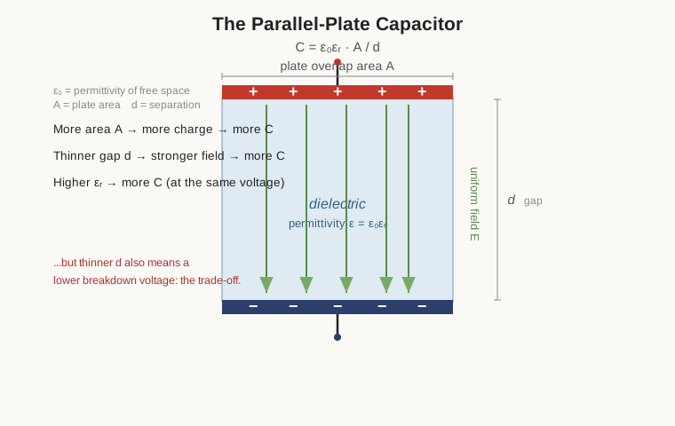
Each term has a plain-English meaning. A is the area of overlap between the plates — literally how much conductor faces conductor. d is the gap between them. And ε (epsilon) is the permittivity of whatever fills the gap: a measure of how readily that material permits an electric field to store charge. Permittivity is conventionally split into two factors, ε = ε₀ · εᵣ. The first, ε₀, is the permittivity of free space, a fixed constant of nature (about 8.85 × 10⁻¹² farads per metre) that sets the baseline for a vacuum. The second, εᵣ, is the relative permittivity or dielectric constant of the filling material — a pure, unitless number telling how many times better than a vacuum that material is at supporting the field. Vacuum is εᵣ = 1 by definition; everything else is larger.
The formula makes three predictions, and all three are true. More area gives more capacitance, because there is simply more plate on which charge can sit — double the overlapping area and double the stored charge at the same voltage. A thinner dielectric gives more capacitance, because bringing the plates closer packs the field lines more tightly and lets each volt hold more charge; capacitance is inversely proportional to the gap. And a higher-permittivity dielectric gives more capacitance, because a material with a large εᵣ lets far more charge sit on the plates at the same voltage than empty space would. These three levers — bigger area, thinner gap, better dielectric — are the only three levers a capacitor designer has, and the entire industry is a chronicle of pulling on them cleverly: rolling huge areas into small cans, growing dielectric layers only atoms thick, and formulating ceramics with staggering dielectric constants.
But the parallel-plate formula also contains the central engineering tension of the whole field, and it is worth stating baldly. Capacitance wants a thin dielectric; voltage rating wants a thick one. The dielectric is not merely an inert spacer — it is an insulator with a finite breakdown strength, a maximum electric field (volts per unit thickness) it can withstand before it fails and lets current punch through, often destructively. Push the plates closer to gain capacitance and the same applied voltage now produces a stronger field across the thinner gap, edging toward breakdown. So a capacitor’s capacitance and its voltage rating are locked in opposition through the thickness d: thin is capacitive but fragile, thick is robust but low-value. Every capacitor on the bench is a specific settlement of that argument, and much of what distinguishes the technologies in later volumes is how good a settlement each dielectric allows.
1.6 Permittivity and the Dielectric Constant
Why should stuffing an insulator into the gap help at all? If the material cannot conduct, how does it increase the charge the plates will hold? The answer is polarization, and it is worth getting an intuition for now even though the physics volume takes it further.
A dielectric is full of charges — electrons bound to nuclei, ions locked in a lattice, whole molecules that may be lopsided — that cannot travel freely but can shift slightly in place. When the capacitor is charged and a field appears across the gap, these bound charges nudge: negative bits lean toward the positive plate, positive bits toward the negative plate. The material develops its own faint internal field pointing against the applied one. The net effect is that the dielectric partially cancels the field the plates produce, so the voltage across the capacitor for a given charge is lower than it would be in vacuum — or, read the other way, more charge can be piled on before the voltage climbs to any given value. More charge at the same voltage is, by Q = CV, exactly more capacitance. The relative permittivity εᵣ is precisely the factor by which a given material boosts the capacitance over vacuum through this polarization.
Some representative values give the lay of the land, and they span an enormous range:
Table 2 — Some representative values give the lay of the land, and they span an enormous range
| Material | Relative permittivity εᵣ (approx.) |
|---|---|
| Vacuum | 1 (exactly, by definition) |
| Air | ~1.0006 (essentially 1) |
| Polypropylene (PP film) | ~2.2 |
| Paper (impregnated) | ~2–4 |
| Polyester / PET film | ~3.2–3.3 |
| Mica | ~5–7 |
| Class I ceramic (C0G/NP0) | ~6 to ~90 |
| Class II ceramic (X7R, etc.) | ~2000–4000 |
| High-εᵣ ceramic (Y5V, Z5U) | up to ~15 000+ |
The table quietly explains a great deal of the component drawer. Film and paper capacitors, with modest εᵣ around 2 to 4, are stable and honest but need large plate areas to reach useful values, which is why a 10 µF film capacitor is a fist-sized brick. Ceramics based on barium titanate reach dielectric constants in the thousands, which is how a multilayer ceramic chip smaller than a grain of rice can also be 10 µF — but that towering permittivity is bought with temperature sensitivity, voltage sensitivity, and aging, the very misbehaviours that force engineers to learn the class codes. The lesson to file away is that dielectric constant is never free: the higher it climbs, the more the dielectric tends to have opinions about temperature, voltage, and time. The reference volume tabulates all of this in one place; here it is enough to know that εᵣ is the knob that separates a stable picofarad-class part from a dense but temperamental microfarad-class one.
1.7 Energy Stored, and Why a Dead Capacitor Can Still Bite
A charged capacitor holds energy, and the amount is:
E = ½ · C · V²
with energy E in joules when C is in farads and V in volts. The factor of one-half appears because the capacitor charges up gradually: the first charge flows in at nearly zero volts and costs almost nothing, while the last charge flows in against nearly the full voltage; averaging over the ramp gives the half. The equation’s most consequential feature is the square on the voltage. Energy scales with the square of the voltage but only linearly with capacitance, so doubling the voltage quadruples the stored energy while doubling the capacitance merely doubles it. Voltage, not capacitance, is what makes a capacitor dangerous.
That energy, as flagged earlier, lives in the field between the plates, not in the plates or the wires. The practical, and occasionally life-or-death, corollary is that the energy does not care whether anything is still connected. A capacitor charged and then disconnected from every source holds its energy silently, sometimes for a very long time, waiting for a conductive path — a screwdriver, a probe, a finger — to appear. It is a battery that a technician assembled by accident and then walked away from.
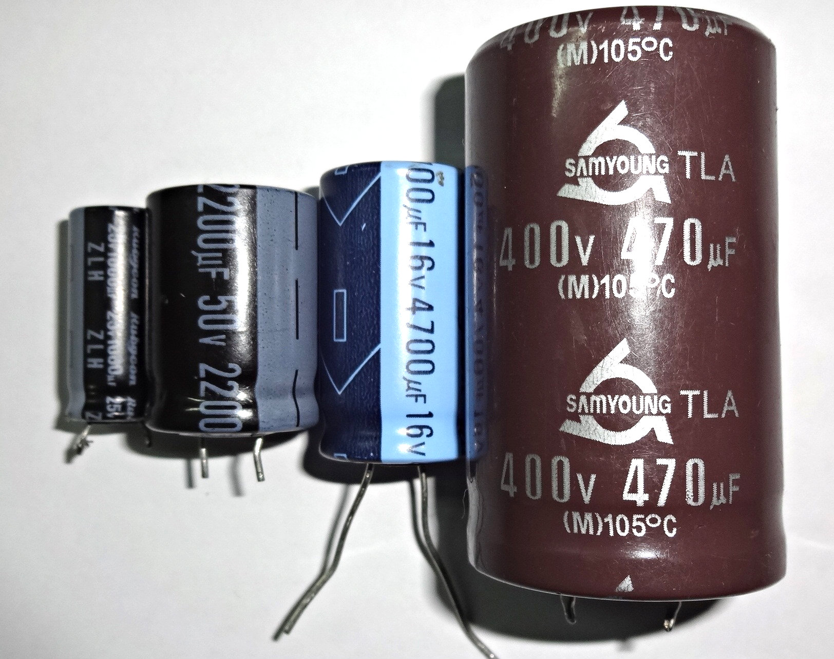
This is not a theoretical hazard. The large electrolytic capacitors in a mains power supply can remain charged to hundreds of volts after the equipment is unplugged; the energy-storage capacitor in a camera flash sits at around 300 volts and will happily arc across a careless hand; the filter and high-voltage capacitors in a tube amplifier or an old CRT television can hold lethal charge for minutes to hours. These parts have injured and killed people who assumed that “unplugged” meant “safe.” The professional habits that answer the hazard are simple and non-negotiable: treat every large or high-voltage capacitor as charged until proven otherwise, and discharge it deliberately before touching it — not with a bare screwdriver across the terminals, which produces a bang, a pit in the blade, and a damaged capacitor, but through a suitable resistor that bleeds the energy away in a controlled second or two. Many well-designed supplies build this in as a permanent bleeder resistor wired across the big capacitor precisely so that the charge drains on its own within a safe interval after power-down. The measurement and safety volume gives discharge procedures the fuller treatment they deserve. The rule for now: a capacitor is the one component that can hurt you after the power is off.
1.8 Charging and Discharging: the RC Time Constant
Capacitors do not charge or discharge instantly through a real circuit, because real circuits contain resistance, and resistance limits how fast charge can move. Put a resistor R in series with a capacitor C and switch on a voltage, and the capacitor voltage does not jump — it approaches the supply along a curve whose entire character is set by a single number, the time constant:
τ = R · C
with τ (tau) in seconds when R is in ohms and C in farads. The time constant is the natural clock of the RC pair. In one time constant, the capacitor charges to about 63% of the way to its final voltage; in the next, it covers 63% of the remaining gap, reaching about 86%; then 95%, 98%, 99.3% at successive time constants. The approach is exponential — always closing a fixed fraction of the remaining distance — so in strict theory it never quite arrives, but engineering is not theology, and the universal rule of thumb is that after five time constants the capacitor is “fully” charged (99.3%, close enough for any practical purpose). Discharge is the mirror image: through a resistor, the voltage falls to 37% of its start in one time constant, and to under 1% after five.
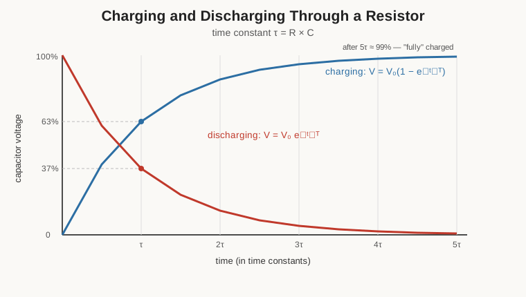
Those two curves are among the most useful shapes in all of electronics, because they turn a capacitor into a device that keeps time and a device that smooths. If a circuit needs to wait a defined interval — a blink, a debounce, a delay — an RC pair charging toward a threshold provides it, and the delay is set simply by choosing R and C so that τ lands where wanted; this is the beating heart of the classic 555 timer and countless one-shots. If a circuit needs to smooth a bumpy voltage, the same lag is repurposed: the capacitor cannot follow fast wiggles because they do not last long enough to charge or discharge it appreciably, so it averages them out, which is exactly what a power-supply filter or a signal low-pass filter does. Timing and filtering are the same exponential seen from two angles, and the applications volume returns to both with real component values. The reader need only carry away the shape of the curve and the fact that τ = RC sets its pace.
1.9 In DC and in AC: Blocking, Passing, and Reactance
The behaviour that most sharply distinguishes a capacitor from an ordinary resistor shows up when the frequency of the applied voltage changes.
Under steady direct current (DC) — a voltage that just sits there — a capacitor charges up to that voltage and then stops drawing current entirely. Once the plates hold all the charge that the voltage will support, there is nowhere for more charge to go, because the dielectric bars the path. So in the DC steady state a capacitor is an open circuit: it blocks direct current. This is exactly the tank with its membrane fully stretched and the flow stopped. The property is enormously useful: place a capacitor in series with a signal and it will pass the wiggling part while blocking any steady DC offset, which is why the component doing that job is called a coupling or DC-blocking capacitor.
Under alternating current (AC) — a voltage that continually reverses — the story flips. Now the capacitor is forever charging one way, then discharging and charging the other, and charge is perpetually sloshing in and out of the plates. Current flows in the external wires the whole time (even though, as always, none crosses the dielectric), so the capacitor passes AC. And here is the elegant part: the higher the frequency, the more readily it passes. This frequency-dependent opposition to AC is called reactance, symbol XC, the capacitor’s analogue of resistance, measured in ohms:
X_C = 1 / (2 · π · f · C)
where f is the frequency in hertz. Read the formula and the behaviour falls out. As frequency f rises, X_C falls — a capacitor looks like less and less opposition to higher frequencies, approaching a short circuit at very high frequency. As f falls toward zero (DC), X_C rises toward infinity — the open circuit already described. A larger capacitance also lowers the reactance at any given frequency. This single inverse relationship is why capacitors are the natural tool for separating signals by frequency: a capacitor happily shunts high-frequency noise to ground while ignoring a low-frequency signal, or couples audio between stages while blocking the DC bias underneath. It is worth stressing that reactance is an idealized picture — it treats the capacitor as storing and returning energy with no loss and no phase confusion, which real parts only approximate. The current in an ideal capacitor actually leads the voltage by ninety degrees, and real capacitors add series resistance and inductance that make their opposition (properly, their impedance) more complicated than a clean 1/(2πfC). The volume on the real capacitor takes up impedance, equivalent series resistance, and self-resonance in full. For an introduction, the load-bearing facts are three: a capacitor blocks DC, passes AC, and opposes AC less as frequency rises.
1.10 Reading the Symbols and the Part
A schematic represents a capacitor with a pair of short parallel lines — a deliberate echo of the two plates — and the small variations in that drawing carry real information.
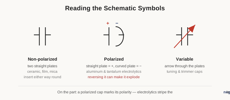
The non-polarized symbol is two straight plates facing each other. It denotes a capacitor with no preferred orientation — ceramic, film, mica — that may be soldered in either way round with no consequence. The polarized symbol keeps one straight plate but draws the other as a curved line, usually with a small plus sign marking the straight plate as positive. It denotes an electrolytic-type capacitor — aluminium or tantalum — that has a definite positive and negative terminal and must be installed the correct way round. The reason is chemistry rather than geometry: these parts hold their vanishingly thin dielectric only because a correctly-directed voltage maintains it, and reversing the polarity destroys that dielectric, which for an aluminium electrolytic means it heats, gasses, and can burst, and for a tantalum can mean a small fire. A backwards electrolytic is one of the classic ways to make a circuit board smell bad. Finally, the variable symbol adds an arrow drawn through the plates, denoting a capacitor whose value can be adjusted — the tuning capacitor of a radio, or a tiny trimmer set once at the factory.
Reading polarity on the physical part is a skill worth drilling, because the two dominant polarized technologies mark themselves in opposite ways, a genuine trap for the unwary. An aluminium electrolytic — the cylindrical can — prints a stripe, usually with minus signs, down the side of the can to mark the negative lead. A tantalum capacitor, by contrast, marks the positive lead, often with a bar or a plus sign. And on parts with unequal leads, the longer lead is conventionally the positive one. The practical drill: on a can with a stripe, the stripe is negative; on a small tantalum with a bar, the bar is positive; when leads differ in length, long is plus. Get this reflex wrong and the board announces it. The volume on reading a capacitor decodes the rest of the markings — the three-digit value codes, tolerance letters, voltage ratings, date codes, and the obsolete coloured-dot systems — but polarity is the one marking that, read wrong, ends the part’s life on the spot.
1.11 Capacitor Versus Battery, in One Breath
Because both a capacitor and a battery store energy and can deliver it later, the two are easily confused, and the differences are exactly the ones that decide which to reach for. A battery stores energy chemically, in reactions that must proceed for current to flow; a capacitor stores energy physically, in an electric field that is already there. The consequences cascade from that one distinction. Chemistry is dense but slow: a battery packs enormous energy into a small mass but can only take it in and give it out at a limited rate, and each charge-discharge cycle wears the chemistry out, so batteries live for hundreds to a few thousand cycles. A field is sparse but instant: a capacitor stores far less energy per gram than a battery, but it can dump or absorb that energy in microseconds and can do so essentially forever — millions of cycles — because nothing is chemically consumed. In a sentence: a battery is a deep, slow reservoir; a capacitor is a shallow, fast one. That is why a phone runs for hours on a battery but the capacitors around its processor exist to supply the sudden bursts of current the battery is too sluggish to deliver. The frontier between the two — the supercapacitor, which uses exotic electrode surfaces to reach farads of capacitance and genuinely begins to blur the line — gets its own treatment in the specialty-capacitor volume.
1.12 How the Trick Is Really Done: Rolling Up the Area
The parallel-plate formula demands area, and a naive capacitor of useful value would need plates the size of tabletops. The industry’s oldest and most durable answer is to take two long, thin metal foils with a thin insulating film between them and roll the whole sandwich into a cylinder, packing an enormous plate area into a small can. Nearly every aluminium electrolytic and film capacitor is built this way; the flat parallel-plate picture is still exactly right, merely wound up.
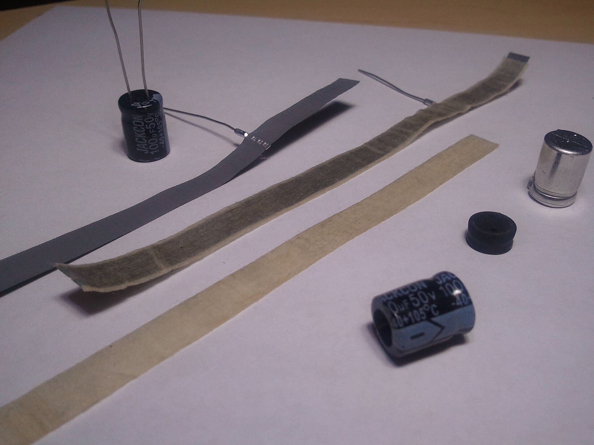
The unrolled electrolytic above shows the strategy laid bare: what looked like a solid metal can is a long spiral of foil and paper, and the dielectric doing the actual insulating is not the visible paper spacer at all but an extraordinarily thin oxide layer grown on one foil — a construction so central to the part that it earns a whole volume of its own. The takeaway for this foundational chapter is only that the drawer full of odd cylinders, blocks, and chips in the first figure are all just clever geometries for the same two-conductors-and-an-insulator idea: rolled foil for electrolytics and film, hundreds of interleaved printed layers for the multilayer ceramic chip, a sintered porous slug for tantalum. Different means, one end — maximise area, minimise gap, choose a dielectric — in service of the single equation C = εA/d.
1.13 Why Anyone Should Care
It would be reasonable, having reached this point, to regard the capacitor as a humble supporting player. The truth is the opposite: by sheer count, the capacitor is the most numerous manufactured component in the modern world. A single high-end smartphone contains on the order of a thousand multilayer ceramic capacitors, and the global industry ships them by the trillions per year. They are everywhere because the handful of behaviours introduced in this volume turn out to be exactly the behaviours electronics constantly needs.
They decouple: parked beside every power pin of every chip, a capacitor acts as a tiny local reservoir that supplies the sudden gulps of current a switching transistor demands, holding the supply voltage steady when the battery or regulator is too far and too slow — the single most common reason a thousand of them cluster on one board. They filter: their frequency-dependent reactance smooths the ripple out of a power supply and strips noise from a signal. They time: paired with a resistor, their exponential charging sets the beat of oscillators, delays, and one-shots. They couple: blocking DC while passing the signal, they carry information from one stage to the next without dragging the bias along. And they store: from the flashgun’s brief brilliant surge to the ride-through capacitor that keeps a system alive through a power blip to the supercapacitor edging into battery territory, they hold energy against the moment it is wanted.
Every one of those roles is a straightforward consequence of a device that stores energy in an electric field between two conductors separated by an insulator — the one sentence from the top of this volume, now doing real work. The volumes that follow take each idea apart: the real capacitor and its imperfections; the history from the Leyden jar forward; how the parts are made and marked; and the technology-by-technology tour that explains why an engineer reaches for a C0G ceramic here, a polypropylene film there, an aluminium electrolytic for bulk, and a tantalum where space is tight. But the foundation is now poured. A capacitor stores charge in a field; Q = CV; capacitance is set by area, gap, and dielectric; energy is ½CV² and it can bite; τ = RC sets the clock; and the part blocks DC while passing AC. Everything else is detail — a great deal of fascinating, occasionally hazardous, endlessly useful detail.
Comments (0)