Capacitors · Volume 8
Aluminum Electrolytic Capacitors: Bulk Storage, ESR, and the Capacitor Plague
8.1 The champion of cheap bulk capacitance
Every family of capacitor is a bargain struck between capacitance, voltage, size, cost, and honesty. The aluminum electrolytic strikes the most lopsided bargain of them all. It offers microfarads by the thousand — capacitance that a ceramic or film part of the same volume cannot begin to reach — for a handful of pennies, and it pays for that gift with almost every other virtue. It is polarized, so it must be installed the right way round or it will vent gas at the reader. Its tolerance is loose, commonly minus-twenty to plus-twenty per cent and sometimes worse. It leaks measurable current even when nothing is wrong with it. Its equivalent series resistance is high and swings wildly with temperature and frequency. And, uniquely among the common capacitor types, it wears out: the thing is slowly dying from the day it is soldered in, and the datasheet quotes the number of hours it has left. No other passive component on the board comes with an expiry clock printed on the side.
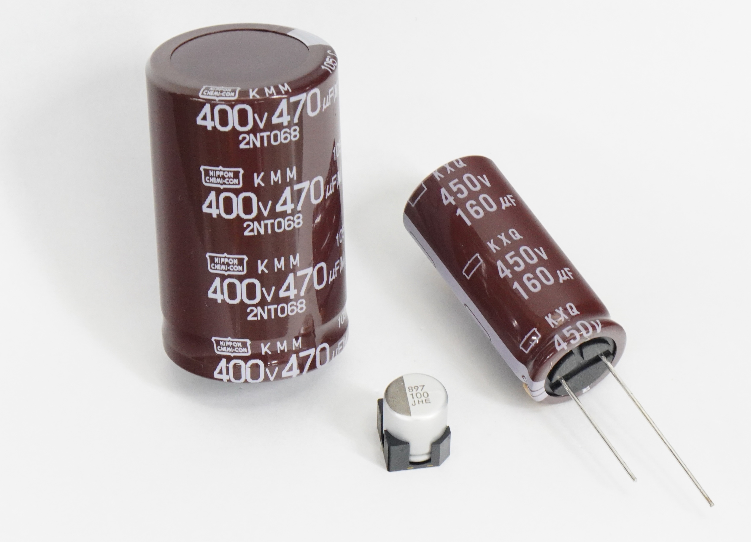
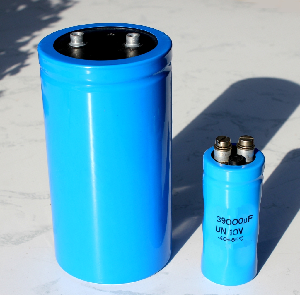
None of that has dislodged it. Open any linear or switching power supply, from a nine-volt wall wart to a kilowatt server unit, and the biggest cans on the board are aluminum electrolytics doing the one job nothing else does as cheaply: bulk energy storage — the reservoir that holds the rail up between the peaks of the rectified mains, and the smoothing capacitor that turns lumpy rectified DC into something a regulator can work with. When a design needs a lot of capacitance to store energy rather than to pass a signal cleanly, and the frequencies involved are low (mains ripple at 100 or 120 hertz, the switching ripple of a converter at tens or hundreds of kilohertz), the electrolytic wins on price and volume by a margin no other family can touch. The engineer’s task is to respect its weaknesses — polarity, ripple heating, and the ticking clock — closely enough that its strengths pay off.
8.2 What it is made of, and why the parts do what they do
The manufacturing volume in this family walks the etch-form-wind process in detail; this volume needs only the finished anatomy, because every electrical quirk that follows falls straight out of it.
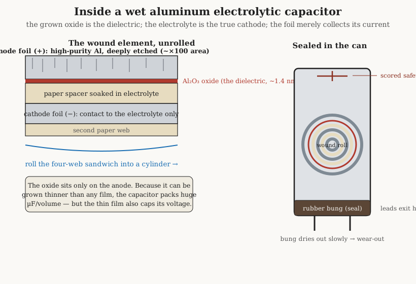
The heart of the part is a strip of very pure aluminum foil, the anode, which the maker has first etched — pitted with a dense forest of microscopic tunnels by an electrochemical bath — so that its true surface area is perhaps a hundred times the area of the flat strip for a low-voltage part, and still several times larger even for a high-voltage one. Onto that vast, cratered surface the maker then grows the dielectric by anodizing: passing the foil through another bath under a DC voltage so that a skin of aluminum oxide, Al₂O₃, forms directly on the metal. This grown oxide is the entire dielectric of the capacitor, and it is astonishingly thin. The film grows at roughly 1.4 nanometres per volt of forming voltage, so a part formed for a four-hundred-volt rating carries an oxide barely half a micrometre thick — around 0.56 µm — and a sixteen-volt part’s dielectric is a couple of dozen nanometres, a film a few hundred atoms deep. Capacitance rises as the dielectric gets thinner and as the area gets larger, and the electrolytic maximizes both at once: a huge etched area carrying a nanometre-scale film. That is the whole secret of its capacitance density, and also the origin of its voltage limit, because a film that thin can only stand so much field before it breaks down.
Here is the point that trips up every newcomer and deserves stating plainly: the second foil is not the other plate. The oxide’s far surface needs to be electrically contacted over every square micrometre of its cratered area, and no solid foil could ever follow the anode into those tunnels. So the real counter-electrode — the true cathode — is a liquid: a conductive electrolyte, soaked into a paper spacer, that flows into every pit and pore and touches the oxide everywhere. The strip of aluminum foil that the schematic thinks of as the negative plate is merely a current collector: a way to make external connection to that electrolyte. It carries a wisp of its own oxide too, which is one reason the cathode side sets a low reverse-voltage tolerance rather than none at all. Understanding that the electrolyte is the cathode explains the part’s entire personality — its resistance, its temperature behaviour, and above all the way it dies, all of which are really the behaviour of a captive puddle of conductive liquid slowly leaving the building.
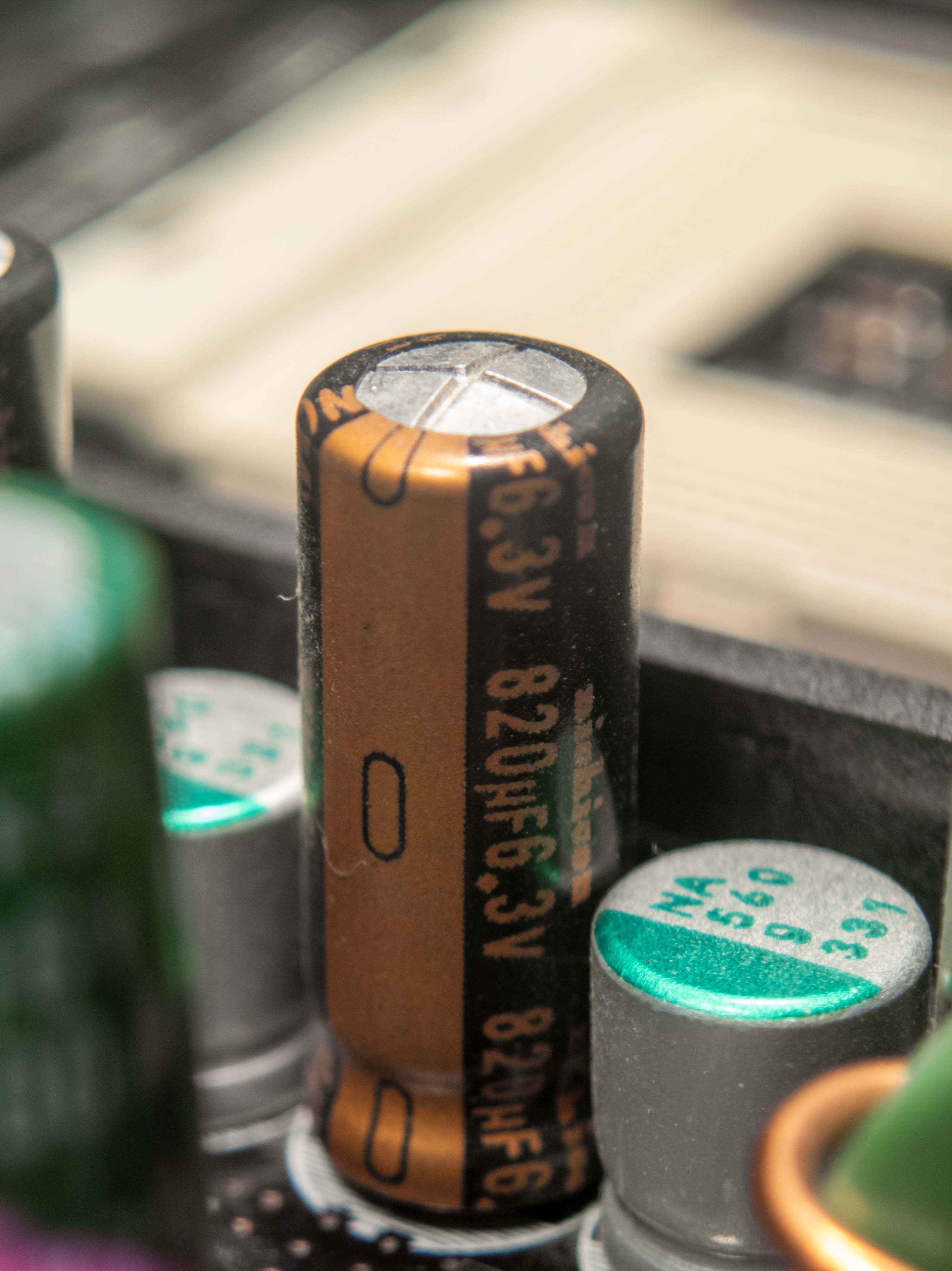
The wound sandwich — etched anode foil, its grown oxide, the electrolyte-soaked paper, and the cathode foil — is rolled into a cylinder, stuffed into an aluminum can, sealed with a rubber bung through which the leads pass, and finished with a safety vent: a set of scored lines pressed into the can (a cross, a K, or a T) engineered to tear open and release gas before internal pressure can turn the can into a projectile.
8.3 Polarity: the one rule you cannot break
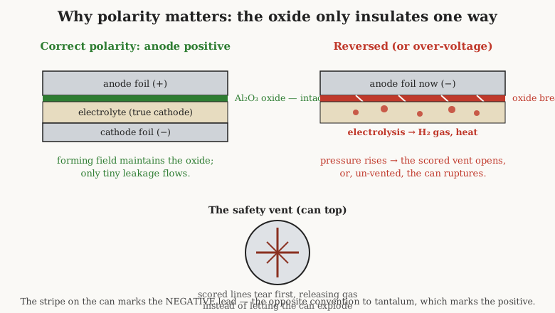
An aluminum electrolytic is polarized because its dielectric is grown, not placed, and grown oxide is a one-way valve. Under the correct polarity — anode positive with respect to the cathode — the forming field is maintained, the oxide stays intact, and only a trickle of leakage current crosses it. Reverse the voltage, or push past the rated voltage in the correct direction, and the oxide can no longer hold off the field. It begins to conduct, the electrolyte starts to electrolyze, and the reaction generates hydrogen gas and heat inside a sealed can. Pressure climbs; the scored vent does its job and splits open, spraying a little electrolyte and a puff of gas, or — in an older part with no effective vent, or a fast enough fault — the can simply ruptures. This is not a rare abuse case; it is the single most common way a hobbyist destroys an electrolytic, usually by installing it backwards on a board or hooking a bench supply up the wrong way.
The marking convention is worth burning into memory because it is the opposite of the other polarized family. On an aluminum electrolytic, the printed stripe down the side of the can marks the negative lead. On a tantalum capacitor (covered in its own volume), the marked stripe or bar denotes the positive terminal. Confuse the two conventions and the part goes in backwards. On radial parts the longer lead is also conventionally the positive (anode) when the leads are still full length, and the can usually has an indented ring near the positive end, but the printed stripe pointing at the negative lead is the marking to trust.
There is one legitimate way to run an electrolytic on alternating current: the non-polar or bipolar electrolytic, built with two anode foils — each carrying a full oxide — wound back to back, with no plain cathode foil at all. Whichever way the instantaneous voltage points, one of the two oxides is forward-biased and blocking, so the part tolerates either polarity. Bipolar electrolytics show up in loudspeaker crossover networks and other audio and AC coupling roles where a large, cheap, non-polar capacitance is wanted and the higher distortion and looser tolerance are acceptable. They pay for their symmetry in size: two oxide films in series means roughly half the capacitance for the same volume as a polarized part.
8.4 The parameters that actually govern the design
The general “real capacitor” volume introduces the parasitics — ESR, ESL, leakage, dissipation factor — that separate a datasheet from an ideal capacitor. On an electrolytic those parasitics are not fine print; they are the whole engineering problem.
8.4.1 ESR: high, and never a fixed number
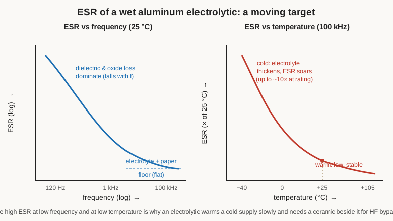
Equivalent series resistance is the lumped resistance in series with the ideal capacitance — the sum of the foil and lead resistance, the oxide loss, and, dominating everything, the resistance of the electrolyte squeezed through the paper. Compared with a ceramic or film part, an electrolytic’s ESR is high: milliohms to a few ohms depending on size and voltage, where a good ceramic sits in the single-digit milliohms. But the number a datasheet prints — always at a stated frequency and temperature — is only one point on a strongly sloped surface.
ESR falls with rising frequency across the low and mid band, because the oxide-and-dielectric loss component is frequency-dependent, then flattens to a plateau in the tens-to-hundreds-of-kilohertz range where the electrolyte-and-paper resistance dominates and is essentially independent of frequency. More consequentially, ESR rises sharply as temperature falls, because the electrolyte is a liquid whose ionic conductivity collapses in the cold. Near a part’s rated low-temperature limit the impedance can be several times, and by some manufacturers’ curves up to ten times, its room-temperature value. This is the mechanism behind the familiar “the equipment won’t start in the cold” failure: a switching supply’s bulk capacitors, stiff and resistive at minus twenty, cannot deliver or absorb current fast enough, the rail sags or the ripple runs wild, and the unit refuses to boot until something warms up. Designers who care about cold starts either specify a part rated for it or over-size the capacitance so the frozen ESR is still tolerable. “Low-ESR” series exist precisely for switching-supply duty, trading a slightly larger can and a higher price for an electrolyte and construction tuned to keep ESR down where the ripple lives.
8.4.2 Ripple current: the rating that really matters
Because ESR is real resistance, any alternating current flowing through the capacitor dissipates power in it as heat: P = I²·ESR, with I the RMS ripple current. In a reservoir or smoothing role that ripple current is the part’s day job — it charges on the rectifier peaks and discharges into the load between them — and the self-heating it produces is the thing that actually cooks the capacitor. So the electrolytic’s headline rating in a power-supply design is not really its capacitance or even its voltage; it is its rated ripple current, the RMS current it can carry continuously at a stated frequency and ambient temperature without the internal (core) temperature climbing past its limit.
It helps to picture the reservoir capacitor’s actual duty. In a classic transformer-rectifier supply the diodes hand the capacitor a series of charge pulses at twice the mains frequency — 100 hertz on a 50-hertz line, 120 on a 60-hertz one — and between those pulses the capacitor alone feeds the load, its voltage sagging a little until the next peak tops it back up. That sag is the ripple voltage, and it shrinks as the capacitance grows, which is why the reservoir wants microfarads by the thousand. But the same current that charges the capacitor on every peak and discharges it into every valley is precisely the ripple current heating it from the inside, and a bigger, lower-ESR capacitor draws sharper, taller charging spikes even as it lowers the ripple voltage. Sizing a reservoir is therefore a three-way negotiation between the ripple voltage the load can tolerate, the ripple current the capacitor can survive, and the peak current the rectifier and transformer can supply — a negotiation the selection volume formalizes and that, on the electrolytic’s side, always comes back to ESR and the heat it makes.
Two subtleties make the ripple rating trickier than a single number. First, because ESR is frequency-dependent, the allowable ripple current is too, and datasheets publish frequency multipliers — a part rated for a given ripple at 100 or 120 hertz can carry substantially more at 100 kilohertz, where its ESR is lower, and the correction factor is tabulated. Second, ripple heating stacks on top of ambient: the core runs hotter than the room by the temperature rise that I²·ESR drives through the can’s thermal resistance, and it is that core temperature, not the ambient, that the lifetime clock reads. Exceed the ripple rating and the core overheats, the electrolyte boils off faster, ESR climbs, which raises the heating further — a thermal-runaway spiral that ends at the vent. This is why the reservoir capacitors nearest a hot rectifier or a warm heatsink are always the first to die.
8.4.3 Leakage and tolerance: high, and mostly fine
An electrolytic’s leakage current — the small DC current that crosses the oxide under rated voltage — is far higher than a film or ceramic part’s, because the oxide is thin and imperfect. It is specified as a small current or as a coefficient times the capacitance-voltage product, and it depends on voltage, temperature, and time: it is largest just after voltage is first applied and then decays over seconds to minutes as the oxide re-forms — the applied field heals the small defects and thin spots in the film, self-repairing the dielectric and dropping the leakage to its steady value. That self-healing property is the same effect exploited deliberately when reforming a long-stored part, discussed below.
A related figure the datasheets quote is the dissipation factor (DF, or tan δ), the ratio of the part’s series resistance to its capacitive reactance at a stated frequency — in effect, ESR expressed as a fraction of the impedance. For an electrolytic the DF is high, often a few per cent to well over ten per cent at 100 or 120 hertz, and it too worsens in the cold. It is the same information as ESR seen from a different angle, and it is the quantity the equivalent-circuit and measurement volumes lean on when they turn the capacitor into a lossy model.
Tolerance is loose — a common grade is −20 %/+20 %, and older or cheaper stock can be −10 %/+50 % or worse — because the etched-and-formed structure simply cannot be controlled to a tight capacitance. For the electrolytic’s real jobs this hardly matters: a reservoir capacitor’s exact value is nearly irrelevant, what counts is that there is enough of it and that it can take the ripple. Nobody builds a precision timing network or a tuned filter out of an aluminum electrolytic, and the loose tolerance is a reason why.
8.5 Wear-out: the clock on the side of the can
The defining property of the wet aluminum electrolytic — the thing that sets it apart from every other capacitor family — is that it has a finite, specified service life, because its liquid electrolyte slowly leaves. The rubber bung is a good seal but not a perfect one; over years, and much faster when hot, the electrolyte’s solvent diffuses out through the seal and the part gradually dries out. As the electrolyte’s volume falls, its resistance rises, so ESR climbs and capacitance drops, until the part no longer meets spec even though nothing has “broken.” That is the wear-out mechanism, and it is why the datasheet quotes a load life: a number of hours at the maximum rated temperature — typically 1,000 to 5,000 hours at 105 °C for a general-purpose part, with long-life and higher-temperature grades reaching well beyond — at the end of which the part is defined as worn out. End-of-life is not a short or an open; it is a specified degradation, conventionally a capacitance drop of, say, twenty per cent or an ESR risen to twice (or some multiple of) its initial value.
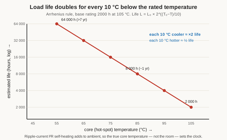
The load-life hours look alarmingly short — a couple of thousand hours is under three months of continuous running — until the temperature dependence is applied, and here the electrolytic’s Arrhenius chemistry turns generous. The rate at which the electrolyte escapes follows the Arrhenius law, which for these parts is captured in a rule every power-supply engineer knows: for every 10 °C the capacitor runs below its rated temperature, its life roughly doubles; for every 10 °C above, it roughly halves. In equation form the estimated life is
L = L₀ × 2^((T₀ − T) / 10)
where L₀ is the rated load life at the rated temperature T₀ and T is the actual core temperature. Run a 2,000-hour, 105 °C part at a 65 °C core and the exponent is four, so life multiplies by sixteen to about 32,000 hours; run it at a 45 °C core and the factor is sixty-four, pushing life past 100,000 hours — well over a decade. This is why a part with a frighteningly short headline rating can nonetheless outlast the equipment, provided it runs cool. The corollary is the design lever that matters: because ripple-current self-heating adds directly to ambient in setting the core temperature, keeping ripple within rating and mounting the capacitor away from hot components is worth more life than any other single choice. It also explains, once more, the field observation that the electrolytics physically closest to the rectifier, the heatsink, or a high-wattage resistor die years before their cooler neighbours on the same board.
8.6 Reforming: waking up old stock
The oxide film is not entirely permanent when idle. In a capacitor that has sat unpowered for years — decades, in vintage equipment — the oxide slowly loses integrity, thin spots and defects developing where the electrolyte has partly chemically reduced it. Apply full rated voltage to such a part cold and the leakage current can be large enough to heat it hard and fast, and a badly degraded part will vent or pop on the spot. The remedy, familiar to anyone who restores tube gear, is reforming: re-growing the oxide by applying voltage gradually, with the current strictly limited, so the film heals faster than the heat can build. In practice the technician ramps the voltage up slowly — often on a variable transformer feeding the whole chassis, or on a bench supply with a series resistor and a firm current limit — pausing at intermediate voltages while the leakage current is watched falling as the oxide re-forms, and only proceeding to full voltage once the leakage has settled to a sane value. Rush it and the reward is a vented can and a lungful of electrolyte.
Reforming is the electrolytic’s contribution to the broader recapping and restoration culture that the paper-capacitor volume describes, but the mechanisms are worth keeping distinct. An old paper capacitor fails because moisture has crept in past its seals and driven its leakage up; the fault is contamination and it is not curable, so the part is simply replaced. An old electrolytic can fail because oxide has degraded and because electrolyte has dried out; the oxide degradation is often curable by reforming, but the dry-out is not — a truly dried-out electrolytic will never come back, and reforming it just confirms the ESR is hopeless. The vintage-restoration instinct to reform is right for storage degradation and useless for genuine dry-out, and the honest move on a decades-old supply is usually to reform what is worth saving and to replace the electrolytics outright where new parts are cheap and the risk is not worth it.
8.7 The Capacitor Plague
For a few years around the turn of the millennium, aluminum electrolytics failed in numbers large enough, and publicly enough, to earn a name: the Capacitor Plague. Between roughly 1999 and 2007, an epidemic of premature electrolytic failure swept through consumer and business electronics — most visibly the motherboards, graphics cards, and power supplies of personal computers, and the switch-mode supplies inside LCD monitors and televisions. The symptoms were unmistakable and physical: capacitors whose flat tops had domed upward into bulges, whose scored vents had split and wept a crusty brown or orange electrolyte residue down the can and onto the board, and, behind those visible signs, capacitance collapsed and ESR sky-high so that the supplies they were meant to smooth went unstable and the machines crashed, failed to boot, or died outright.
The cause was not wear-out or abuse but a defective electrolyte formulation, and the story behind it is nearly operatic. The widely reported account traces it to a stolen and, crucially, incomplete electrolyte recipe: a materials scientist is said to have taken a water-based electrolyte formula from a Japanese manufacturer to a firm in China, from which staff in turn carried a copied version to a number of Taiwanese capacitor makers, undercutting the established Japanese suppliers on price. The copied formula lacked proprietary additives — the inhibitors that suppress corrosion and, in particular, keep the water-based electrolyte from generating hydrogen gas at the aluminum. Packaged into finished capacitors, the flawed electrolyte was chemically unstable: it corroded the foils and generated gas in normal service, so the parts built up internal pressure, bulged, vented, and lost capacitance long before their rated life — often within months to a year or two of use. Most affected parts were made from about 1999 to 2003 and failed between roughly 2002 and 2005, with stragglers in equipment built as late as 2007. The scale was enormous: major vendors recalled and reworked boards by the millions, and one large PC maker is reported to have spent on the order of US$420 million dealing with the fallout on its systems alone.
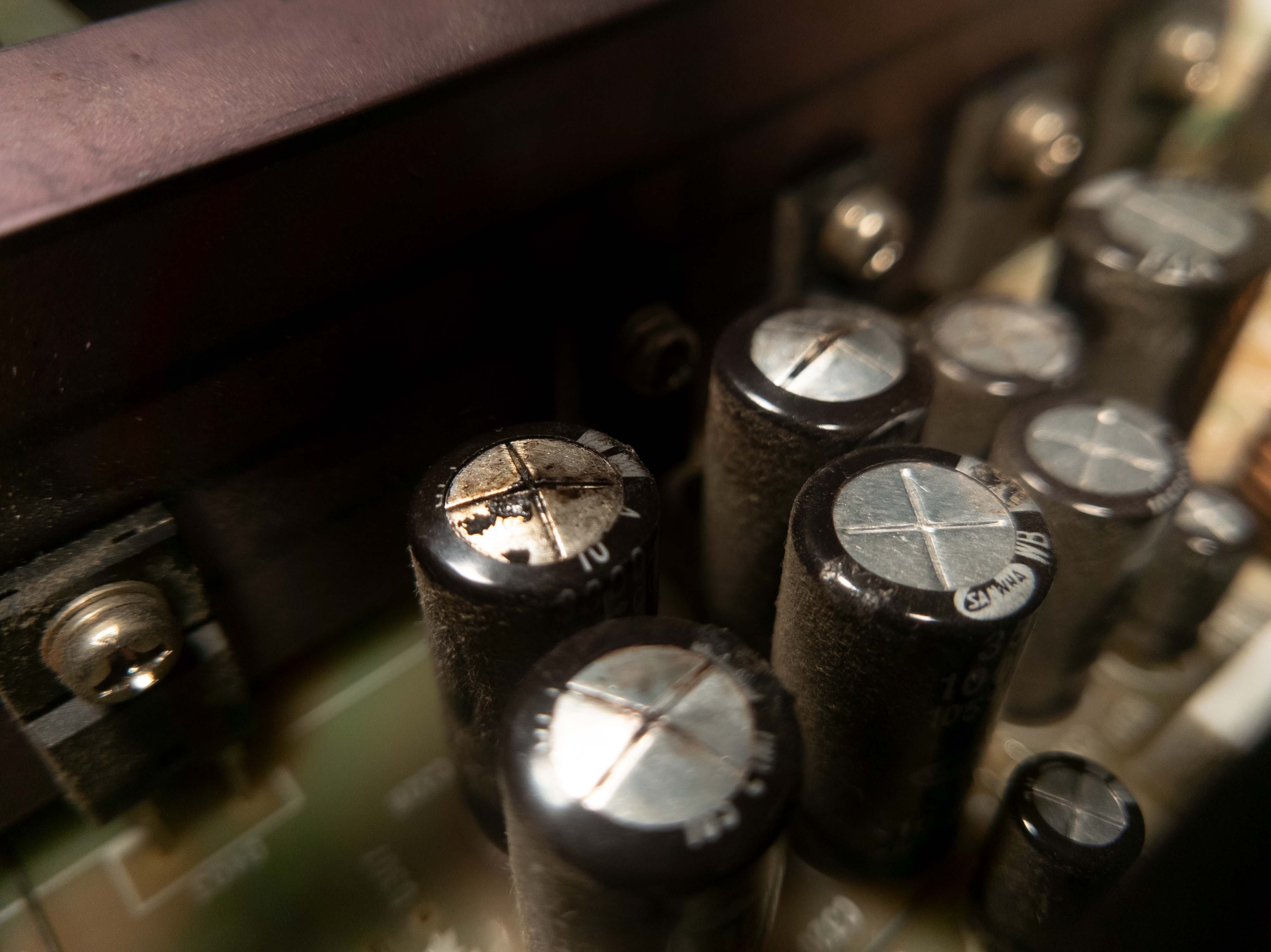
The Plague’s lasting legacy is cultural as much as technical. It taught a generation of hobbyists and technicians to read the tops of the capacitors first when a board misbehaves, and it turned recapping — desoldering the swollen electrolytics and fitting fresh, good-brand, low-ESR replacements — into a mainstream repair hobby, keeping a great deal of otherwise-scrapped equipment alive. It also hardened the industry’s preference for reputable Japanese electrolytic brands in anything that matters, and it accelerated the move to solid electrolytes in exactly the high-ripple, hot-running roles — computer motherboards and voltage regulators — where the wet parts had failed most spectacularly.
8.8 Polymer and hybrid electrolytics: the solid-state answer
The wet electrolytic’s every serious flaw — high ESR, cold-weather ESR blow-up, and dry-out wear-out — traces to the same source: the cathode is a liquid. Replace that liquid with a solid conductive polymer (typically a doped organic conductor such as PEDOT) and most of those flaws recede at once. The polymer aluminum electrolytic keeps the same etched, oxidized anode foil — so the capacitance-per-volume and the polarity are unchanged — but the cathode is now a solid conductive film. Because that film is far more conductive than any wet electrolyte, ESR drops dramatically, into the low single-digit or even sub-milliohm range for a comparable part, with correspondingly higher ripple-current capability. Because there is no solvent to evaporate, the classic dry-out wear-out mechanism largely goes away, so rated lifetimes lengthen and the ESR barely moves with temperature — the cold-start problem all but vanishes. The costs are real: polymer parts are more expensive, are generally limited to lower voltages (roughly up to the tens of volts, though the ceiling keeps rising), and have higher leakage than their wet cousins, and a solid polymer cannot self-heal a punctured oxide by re-forming the way a wet electrolyte can, so their failure modes differ.
The hybrid polymer capacitor splits the difference cleverly: it uses a conductive polymer and a small amount of liquid electrolyte together. The polymer delivers the low ESR and high ripple, while the residual liquid keeps the oxide healable — restoring some of the wet part’s self-repair and pushing the voltage rating back up — and gives lower leakage than an all-polymer part. Hybrids reach usefully higher voltages than pure polymer (into the tens of volts and beyond), tolerate high temperatures, and boast long life; they have become a favourite in automotive electronics and other hot, high-reliability, high-ripple settings.
Where the money and the physics allow, solid and hybrid parts have displaced wet electrolytics wholesale — the low-voltage VRM (voltage-regulator module) capacitors clustered around a modern CPU are almost all polymer, and quality motherboards advertise “all solid capacitors” precisely as a post-Plague reassurance. Where wet electrolytics still win is the territory polymer cannot yet reach cheaply: high voltage (the hundreds-of-volts bulk reservoir on a mains rail), high bulk capacitance for the money, and applications where the cost of a polymer part is not justified. The primary-side bulk capacitor smoothing rectified mains in a power supply is still, overwhelmingly, a wet aluminum electrolytic.
8.9 Where it wins, where it loses, and the ceramic beside it
Placed against the alternatives, the aluminum electrolytic’s niche is sharp. It beats ceramics and film on bulk capacitance per unit cost and per unit volume by a wide margin, which is why it owns the reservoir and smoothing roles. It loses to them on tolerance, leakage, high-frequency performance, and lifespan, and to film on ripple-handling per volume in the harshest AC-line roles, and to both on longevity in anything expected to run for decades untouched.
The high-frequency loss deserves a closing note because it drives a layout habit every power-supply designer follows. An electrolytic’s own parasitic inductance (ESL) and its ESR make its impedance rise and its usefulness fall well before the megahertz region; it is excellent at holding up a rail against slow, heavy, low-frequency demands and useless at swallowing the fast current spikes a digital load or a switching node throws off. So the standard arrangement is to pair an electrolytic with a small ceramic: the electrolytic handles the bulk, low-frequency ripple and energy storage, while a ceramic (or several) placed right at the load handles the high-frequency bypass that the electrolytic’s ESR and ESL cannot. The two are not competitors here but a team — the big slow tank and the small fast one — and the selection volume treats when and how to size each.
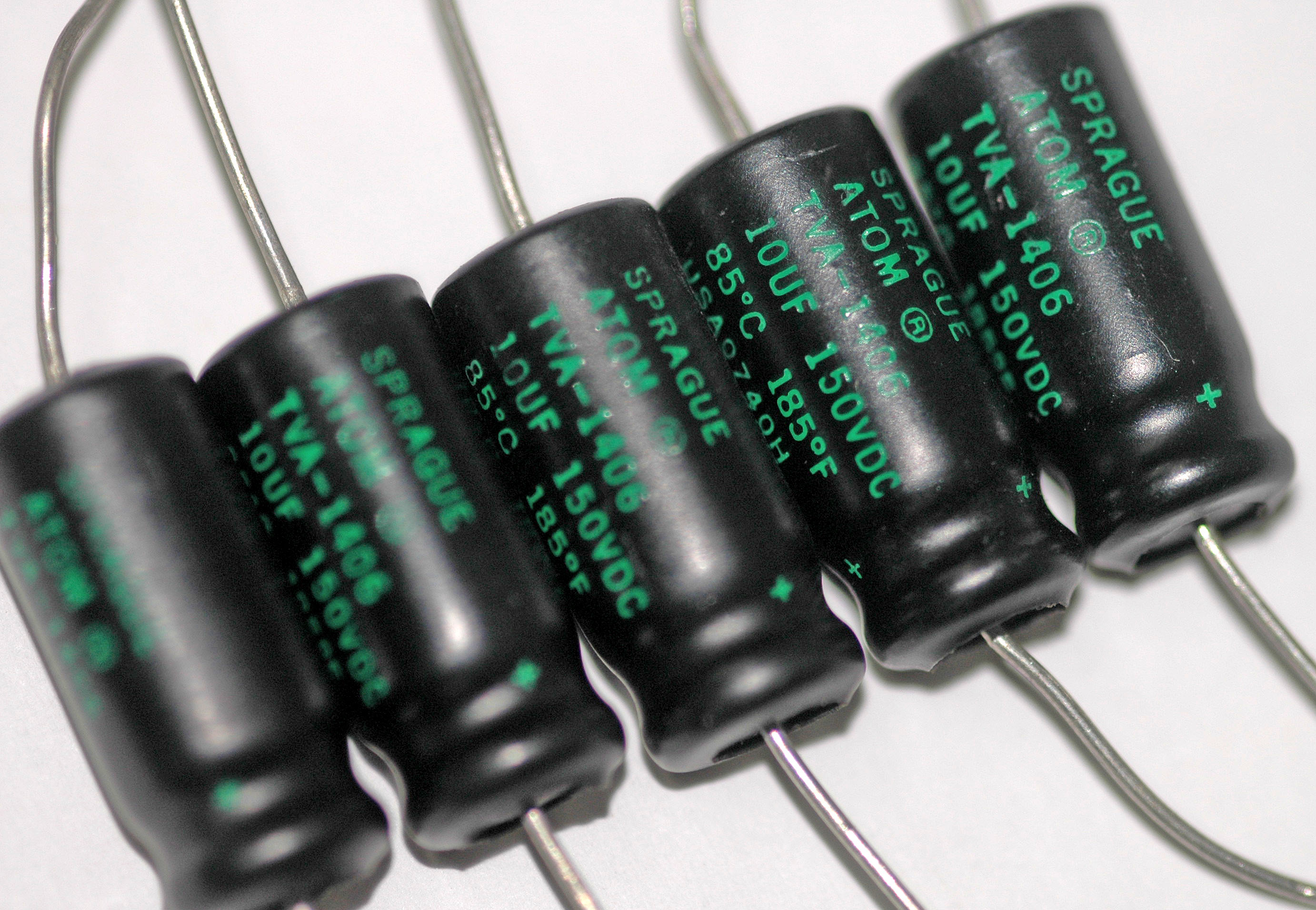
8.10 At the bench: spotting, judging, and replacing an electrolytic
For a working technician the electrolytic is the component to suspect first when powered equipment behaves badly — instability, hum, intermittent faults, a supply that will not start, a display that flickers or takes a long time to come up. The diagnostic routine is quick and mostly visual.
Look first. A healthy electrolytic has a flat top. A domed, bulged, or split top is a condemned part, full stop — replace it and its neighbours without further testing. Look also for crusty or discoloured electrolyte residue weeping from the vent or pooled around the base on the board, and for a bulged rubber bung at the bottom on radial parts. On a board hit by the Plague or by heat, whole rows of the same value will often be swollen together.
Then measure. The two numbers that matter are capacitance (should be within tolerance, and a large drop condemns the part) and ESR, which is the more sensitive early warning: a dedicated ESR meter reads the equivalent series resistance, often usefully in-circuit, and an ESR that has risen well above the datasheet value — or well above a known-good sister part — means a dried, dying capacitor even when the top still looks flat and the capacitance still reads roughly right. The measurement volume covers ESR meters and in-circuit testing technique in detail; the practical point here is that ESR catches wear-out before capacitance does. Do not trust a simple capacitance check alone to clear an electrolytic.
When to recap wholesale. If a board shows several failed electrolytics, or is of an era and brand known for the Plague, or has simply run hot for many years, the economical move is to replace all the electrolytics at once rather than chase them one at a time — they have aged together and the survivors are not far behind, and the labour of opening the equipment dwarfs the pennies the capacitors cost.
Choosing the replacement. The rules are few and firm. Match or exceed the voltage rating (never go below; higher is fine and often more reliable). Prefer 105 °C parts over 85 °C ones for the extra thermal headroom and life. In any switching supply, use a low-ESR series and check the ripple-current rating meets or beats the original — an ordinary general-purpose part dropped into a switcher’s output will overheat and fail early however “correct” its capacitance and voltage look. Match the capacitance (a modest increase is usually harmless in a reservoir role, but large increases can stress a rectifier’s inrush). Mind the physical size and lead spacing so the part fits the footprint and the can clears its neighbours and the lid. And — the warning that bookends this whole volume — observe polarity: the stripe is the negative lead, in goes the right way round, and a moment’s inattention there is the difference between a repaired board and a vented can.
Respect the polarity, keep it inside its ripple rating, and mount it where it can stay cool, and the humblest, cheapest, shortest-lived capacitor on the board will quietly outlast almost everything around it. Ignore any one of those three, and it will tell the reader — loudly, and with a smell.
Comments (0)