Capacitors · Volume 7
Film Capacitors: Polyester, Polypropylene, and the Self-Healing Trick
7.1 The quality capacitor of the analog world
A film capacitor is, at heart, the oldest idea in the whole component family dressed in a modern material. Take a thin sheet of plastic — the dielectric, the insulator that does the actual work of holding charge apart — put a conductor on each face of it, and roll or stack the sandwich until a large facing area lives in a small package. That is the same recipe the eighteenth century used with a glass jar and the early twentieth century used with waxed paper. What changed is the middle layer. Somewhere in the 1950s the industry learned to make dielectric films out of engineered plastics — first polyester, then polypropylene and a small menagerie of others — and those plastics turned out to be so much more stable, so much cleaner electrically, and so much more tolerant of a manufacturing flaw than paper ever was that the film capacitor quietly became the reference-grade passive of the analog world.
That phrase deserves unpacking, because it is the reason this class of part still exists in an age of ceramic chips a thousand times smaller. A film capacitor is non-polar, meaning it does not care which way round it is connected — unlike the aluminum electrolytic, which will vent if reversed. Its capacitance barely drifts with applied voltage, unlike the Class II ceramic covered in the ceramics volume, whose value can collapse by half under DC bias. Its losses are low and its dielectric absorption — the maddening tendency of a capacitor to “remember” a charge and creep back to a fraction of its old voltage after being shorted, discussed at length in the real-capacitor volume — is among the lowest of any technology. It self-heals a minor breakdown instead of dying from it. And it lasts: a decent film cap sitting in a signal path will outlive the equipment around it. The price of all this virtue is size and cost. A film capacitor is bulky and expensive per microfarad next to a ceramic or an electrolytic, and it cannot come anywhere near the bulk capacitance of an electrolytic can. It is the part an engineer reaches for when the job demands stability, low loss, pulse handling, or a value that must not lie — and can afford the board space to get it.
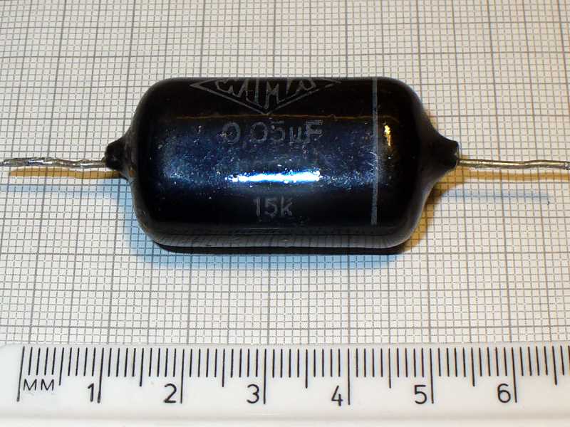
The rest of this volume is organized around the questions an engineer actually asks at the parts bin. How is the thing built, and why are there two very different constructions hiding behind the same rectangular case? What is the self-healing trick, why does it matter, and what does it cost? Which plastic should the dielectric be — polyester, polypropylene, polystyrene, PPS, something exotic — and where does each one win? What are those X- and Y-rated “safety capacitors” bolted across the mains, and why must they never be substituted with an ordinary part? And finally, where does film beat the alternatives, and where does it lose?
7.2 Two constructions behind one case
Two film capacitors can sit in identical rectangular boxes, carry the same printed value, and behave quite differently under stress, because there are two fundamentally different ways to put the electrodes onto the plastic. The distinction — film/foil versus metallized film — is the single most important thing to understand about the family, and nearly every other property flows from it.
7.2.1 Film/foil: the electrode is a separate metal sheet
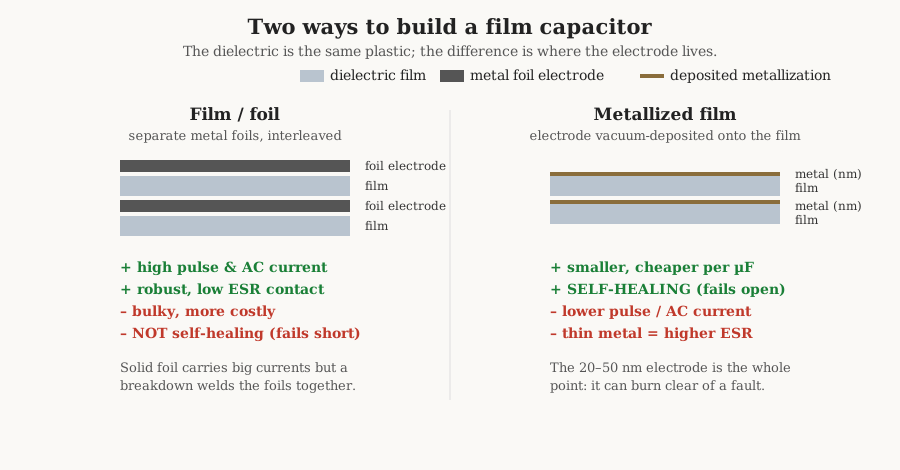
In the older and more rugged construction, the electrode is exactly what it was in a paper capacitor: a discrete sheet of thin metal foil, usually aluminum, interleaved with the plastic dielectric and wound or stacked into the element. The manufacturing details — winding on a mandrel, the extended-foil or inserted-tab end connection, the end-spray metal contact known as schoopage — are covered in the manufacturing volume. What matters electrically is that the electrode is a solid, comparatively thick conductor. A solid foil can carry a large current without heating, makes a low-resistance connection to the terminals (low equivalent series resistance, the parasitic resistance that turns ripple current into heat), and shrugs off steep voltage edges. Film/foil is therefore the construction of choice where the cap must pass heavy pulse or high-frequency AC current, or where the utmost reliability is wanted and the designer will pay in size for it.
The cost of the solid foil is exactly its solidity. There is no self-healing — more on that in a moment — and the part is physically larger, because a foil electrode cannot be made anywhere near as thin as a deposited film, and because it demands its own margins and handling. Film/foil is the premium, low-volume corner of the market: precision, pulse, and high-current parts, and a good deal of the polystyrene and PTFE range where absolute performance is the whole point.
7.2.2 Metallized film: the electrode is sprayed onto the plastic
The construction that made film capacitors cheap and small does away with the separate foil entirely. Instead, a whisker-thin layer of metal — aluminum, or zinc, typically only 20 to 50 nanometers thick, a hundredth of the thickness of household foil — is vacuum-deposited directly onto the surface of the plastic film, the way a mirror is silvered. The metallized film is the electrode; the plastic carries its own conductor on its back. Two such metallized films (or one metallized film and a bare one, metallized on the correct faces) are wound together, and the result is dramatically smaller and cheaper than the film/foil equivalent of the same value, because the electrode adds almost no thickness and no separate material to handle.
The catch is that a 30-nanometer film of metal is a poor conductor of bulk current. Its sheet resistance is far higher than a foil’s, which raises ESR and limits how much AC or pulse current the part can pass before the electrode itself overheats. So metallized film trades current capability and a little contact quality for size, cost, and — the reason it dominates the market — a genuinely remarkable failure behavior that the foil construction simply cannot offer.
7.3 The self-healing trick
Here is the property that defines the metallized film capacitor and, more than any single number, explains why it is everywhere.
Every capacitor has weak spots in its dielectric: a pinhole, a thin patch, an embedded contaminant, a place where the plastic is a micron thinner than its neighbors. Push the voltage high enough — from an over-voltage event, a mains surge, or simply the statistics of a large area of very thin film — and the weakest spot breaks down. A tiny arc punches through the dielectric at that point, a short between the two electrodes.
In a film/foil capacitor that is very often the end. The arc has two thick, solid conductors on either side of it, and with real current available it welds them together into a permanent short. The cap is dead, and worse, it has failed short — a low-resistance path that can dump the rest of the circuit’s energy through the fault.
In a metallized film capacitor the same breakdown is a non-event. The moment the arc strikes, its heat lands not on a robust foil but on the micron-thin deposited electrode — and that whisker of metal simply boils away. The arc vaporizes the metallization in a small circle around the point of breakdown, typically fractions of a millimeter across, stripping the electrode back from the fault and leaving a clean, demetallized ring of bare plastic. The defect is now surrounded by insulation with no electrode reaching it; it is electrically cut out of the circuit. The whole event — arc, vaporization, isolation — is over in under about ten microseconds, frequently without so much as interrupting the capacitor’s operation. The industry calls it self-healing, or, more precisely, clearing.
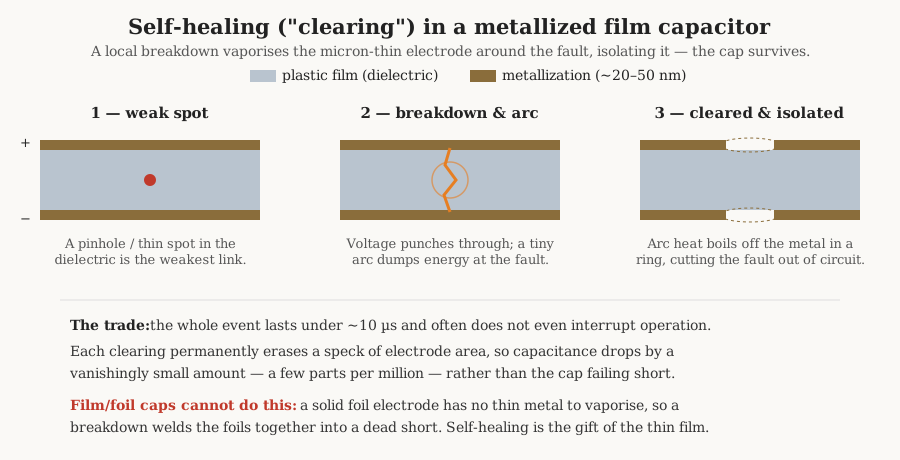
Self-healing is not free, but its price is almost comically small. Each clearing permanently erases a speck of electrode area, so the capacitance drops — by a few parts per million per event, an amount that would take a great many clearings to matter. A metallized film capacitor therefore ages gracefully under electrical stress where a foil part fails catastrophically: it trades a vanishing sliver of its value for continued life. This is precisely the behavior a designer wants in the two places film caps earn their keep hardest — hanging on a mains line, where a failure must not become a short, and inside a power converter, where surges are routine. Metallized construction is why the line-connected safety capacitors discussed later can be trusted to fail open, and it is one of the half-dozen genuinely elegant ideas in passive-component engineering.
There is a subtlety worth flagging for the bench. Self-healing needs a little energy to do its job — the arc has to have enough behind it to actually vaporize the metal cleanly. At very low voltages, or with a very soft source, a defect can sometimes fail to clear properly and instead simmer, and this is one of the mechanisms behind the notorious slow death of cheap mains-suppression capacitors, taken up in the safety-cap section. Manufacturers tune the metallization pattern for this: many parts use a segmented or T-margin metallization, dividing the electrode into a grid of tiny areas linked by narrow fuse-like gates, so that a fault that will not clear instead isolates its whole small segment. The graceful-failure philosophy runs all the way down.
7.4 The dielectric menu
With construction understood, the remaining choice is the plastic itself, and this is where the family splits into named types. Each dielectric is a different compromise between four things a designer cares about: permittivity (the relative permittivity ε_r, which sets how much capacitance a given area buys — higher means a smaller cap), maximum temperature, loss (the dissipation factor, tan δ, the fraction of energy burned per cycle), and dielectric absorption (the soakage that ruins precision timing and sample-and-hold circuits). No single plastic wins every column, which is exactly why the menu has more than one item on it.
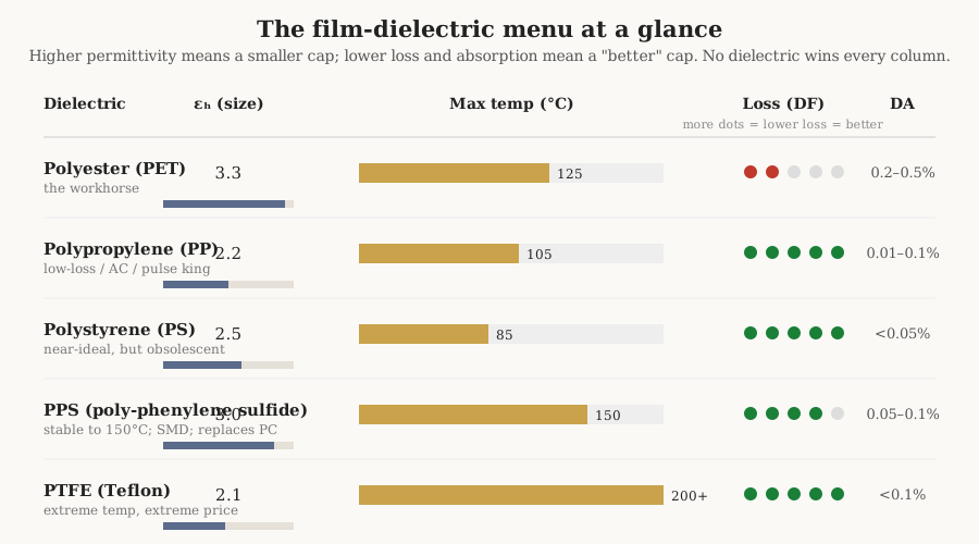
The table below collects the working numbers. They are ranges, not points, because they depend on film thickness, frequency, and the exact grade — but they are the ballpark an engineer should carry.
Table 1 — The dielectric menu
| Dielectric | Common codes | ε_r | Max temp | DF @ 1 kHz | Dielectric absorption | Where it wins |
|---|---|---|---|---|---|---|
| Polyester / PET (Mylar) | MKT, KT | ~3.3 | −55 to +125 °C (grades to +150) | ~50–200 ×10⁻⁴ | ~0.2–0.5 % | The cheap, small, general-purpose workhorse |
| Polypropylene / PP | MKP, KP, FKP | ~2.2 | −55 to +105 °C | ~0.5–5 ×10⁻⁴ | ~0.01–0.1 % | Low loss, high dV/dt, AC and pulse |
| Polystyrene / PS | KS | ~2.5 | −55 to +85 °C | very low (~1–5 ×10⁻⁴) | <0.05 % | Precision timing/filters (obsolescent) |
| PPS | — | ~3.0 | −55 to +150 °C | ~2–15 ×10⁻⁴ | ~0.05–0.1 % | Temperature-stable, SMD; replaces polycarbonate |
| PTFE / Teflon | — | ~2.1 | to +200 °C+ | ~2 ×10⁻⁴ | <0.1 % | Extreme temperature, lowest loss (niche, costly) |
7.4.1 Polyester (PET, Mylar): the workhorse
Polyethylene terephthalate — PET, sold under the DuPont trade name Mylar, and coded MKT for the metallized version — is the film capacitor most people have actually held. It is the little green or tan boxed cap potted in epoxy that fills coupling, bypass, and timing sockets in nearly every piece of analog gear built since the 1960s. Its appeal is entirely practical. Of the film dielectrics it has the highest permittivity, about 3.3, which — combined with a high dielectric strength that lets the film be made pleasingly thin — makes it the smallest and cheapest film cap for a given value. It tolerates a useful temperature range, comfortably to 125 °C and with special grades to 150 °C, and it absorbs very little moisture.
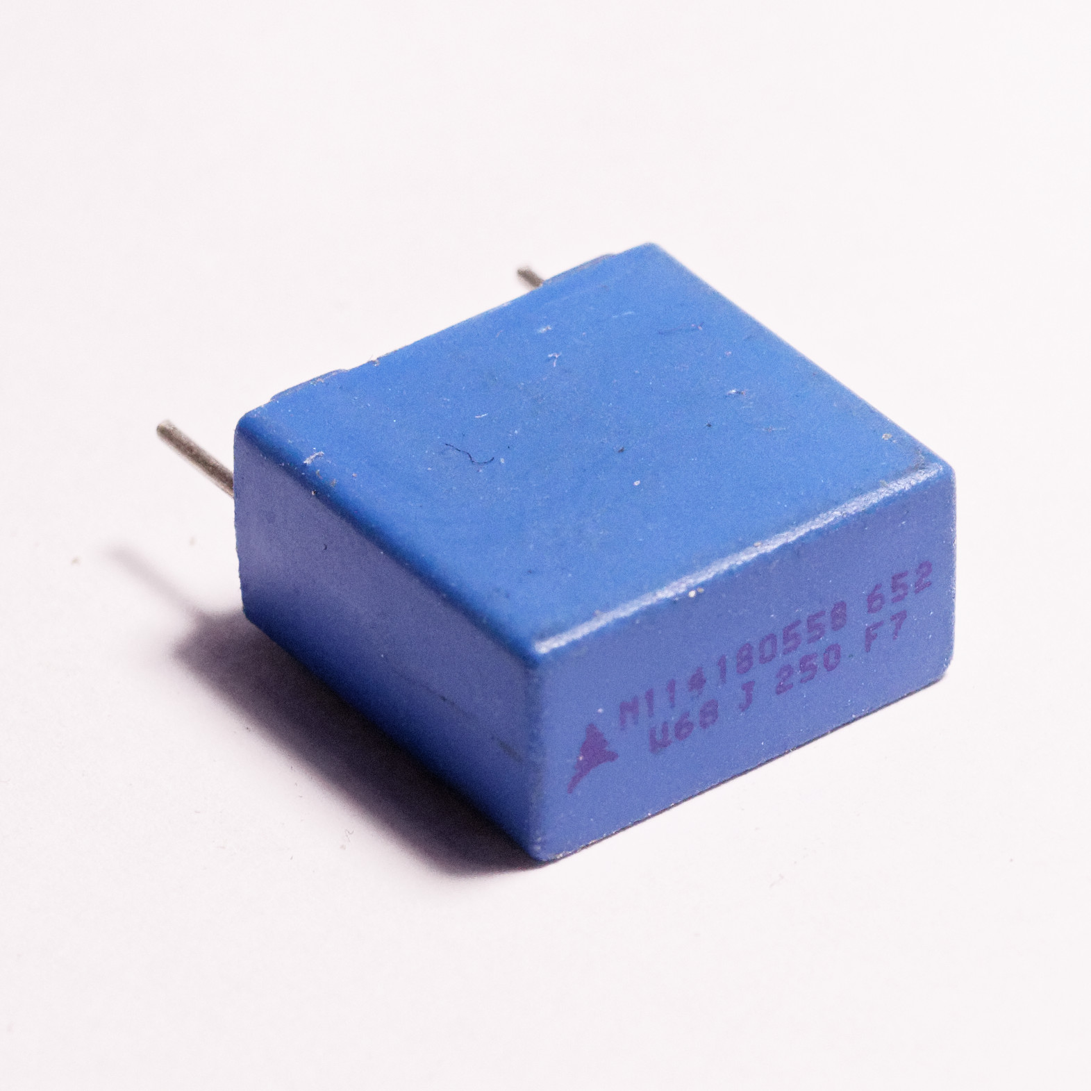
What polyester gives up is electrical cleanliness. Its dissipation factor is an order of magnitude worse than polypropylene’s and it climbs with frequency, so PET is a poor choice for heavy AC current, snubbers, or steep pulse duty — the losses simply turn into heat. Its dielectric absorption, a few tenths of a percent, is fine for coupling and bypass but disqualifies it from precision integrators and sample-and-hold. In short, polyester is the part a designer specifies when the job wants a stable, non-polar, self-healing capacitor and does not want ceramic’s voltage-dependence or an electrolytic’s polarity — and does not need the last word in loss. That covers an enormous fraction of everyday analog design, which is why the green box is ubiquitous. It is also, not coincidentally, the modern part that most often replaces an old paper capacitor in a restoration: same non-polar wound construction, same footprint, vastly better stability and leakage, and covered in detail in the paper-capacitor volume.
7.4.2 Polypropylene (PP): the engineer’s and audiophile’s favorite
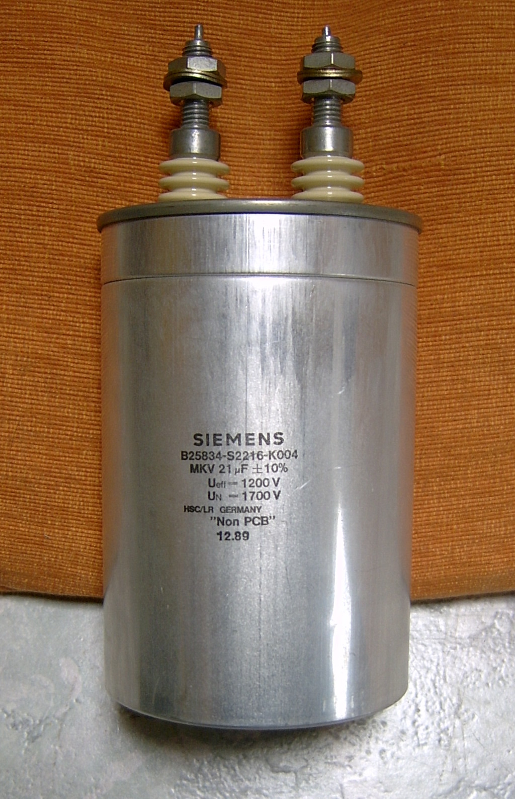
If polyester is the workhorse, polypropylene — MKP metallized, KP or FKP in film/foil — is the thoroughbred, and it is the dielectric an experienced engineer reaches for the moment the application turns demanding. Its permittivity is low, only about 2.2, so a PP cap of a given value is noticeably bigger than the polyester equivalent. Everything else about it is excellent. Its dissipation factor is extraordinarily low — a fraction of a milliradian, an order or two of magnitude better than PET — and, crucially, it stays low and flat across frequency and temperature. Its dielectric absorption is among the lowest of any practical dielectric. It withstands very high dV/dt (rate of change of voltage — the steepness of the edges it can handle without excessive current) and high AC current, and its dielectric strength is the highest of the common films.
That combination makes polypropylene the default for essentially everything that stresses a capacitor electrically: snubbers across switching devices, resonant and LC tank circuits, the primary and filter capacitors in switched-mode power supplies, lighting ballasts, audio crossovers, motor-run duty, and mains filtering. It is also the audiophile’s darling, for the perfectly defensible reason that low loss and low absorption really do make it the most electrically transparent film available; the audiophile then frequently pays for a boutique film/foil PP part that measures indistinguishably from a good MKP, but that is a different volume’s argument. The engineer’s version of the same fact is simply this: when a film cap has to work rather than merely couple a signal, it is almost always polypropylene.
7.4.3 Polystyrene (PS): near-ideal, and nearly gone
Polystyrene — coded KS, and made almost exclusively in film/foil — is the dielectric the precision world loved and the manufacturing world abandoned. Electrically it is close to ideal: dissipation factor is minute, dielectric absorption is exceptionally low (well under a tenth of a percent, low enough for demanding sample-and-hold and integrator work), and its temperature coefficient is small, stable, and negative — about −125 ppm/°C. That negative tempco is a quietly beautiful property, because it can be paired with the positive temperature coefficient of a typical inductor to build an LC filter or oscillator whose frequency barely moves with temperature; a generation of precision active filters and timing circuits was built on exactly that trick.
The problem is thermal. Polystyrene softens at low temperature; its practical ceiling is only around 85 °C, and it takes a permanent set — a permanent shift in value that does not recover on cooling — if pushed much past 70 °C. It also cannot be made as thin as the newer films. As component temperatures rose and boards shrank, that ceiling became disqualifying, and by the 2010s polystyrene film had been largely discontinued in favor of polyester and, for the precision niche, PPS. It remains worth knowing for two reasons: vintage precision equipment is full of it, and a few specialist suppliers still make it for filter and timing work where its absorption and tempco genuinely cannot be matched by anything cheaper.
7.4.4 PPS: the modern precision film
Polyphenylene sulfide — PPS — is the dielectric that inherited the precision throne polystyrene and polycarbonate vacated. Its permittivity is a useful 3.0, its dissipation factor is low and, more importantly, remarkably flat over temperature and frequency, and its capacitance is stable to roughly ±1.5 % across a wide range with a small, predictable temperature coefficient. It handles up to about 150 °C, it absorbs almost no moisture, and — the property that secured its future — it can be made as a surface-mount chip. When polycarbonate film (once the standard temperature-stable precision dielectric) was discontinued around the turn of the century after the sole film supplier exited the business, PPS was the part the industry moved to. For an SMD precision timing, filter, or temperature-critical role today, PPS is the film answer.
7.4.5 Polycarbonate and PEN: the ones that came and went (mostly)
Two more names appear often enough in datasheets and vintage bills of materials to deserve a line each. Polycarbonate (PC) film was, for decades, the standard temperature-stable precision dielectric — low loss, tight and predictable temperature coefficient, good to around 125 °C — and it is the part PPS displaced. Its disappearance was not an engineering verdict but an industrial accident: the sole manufacturer of capacitor-grade polycarbonate film exited the business around the year 2000, and with no film to buy, the capacitor makers simply stopped. A designer meeting polycarbonate today is almost always looking at an old design, and the modern substitution is PPS. PEN (polyethylene naphthalate) is a close relative of polyester with a higher temperature ceiling (to about 150 °C) and slightly lower permittivity; it fills a niche as a higher-temperature, SMD-capable polyester alternative but has never been as widespread as PET itself.
7.4.6 PTFE and the exotics
At the far end sit PTFE (Teflon) and a handful of other high-performance fluoropolymer and specialty films. PTFE offers the lowest loss of all, essentially flat to very high frequency, and operating temperatures beyond 200 °C. It is used where nothing else survives — aerospace, downhole, extreme RF — and it is expensive, bulky, and firmly niche. The engineer meets it rarely and pays for it dearly when the datasheet leaves no alternative.
7.5 Safety-rated film caps: Class X and Class Y
There is one application where the choice of a film capacitor is not merely an engineering preference but a matter of law, certification, and physical safety: the capacitors connected directly to the AC mains. These are the safety capacitors, and they are governed by the standard IEC 60384-14, which sorts them into two classes — X and Y — according to what happens to a human being if the capacitor fails.
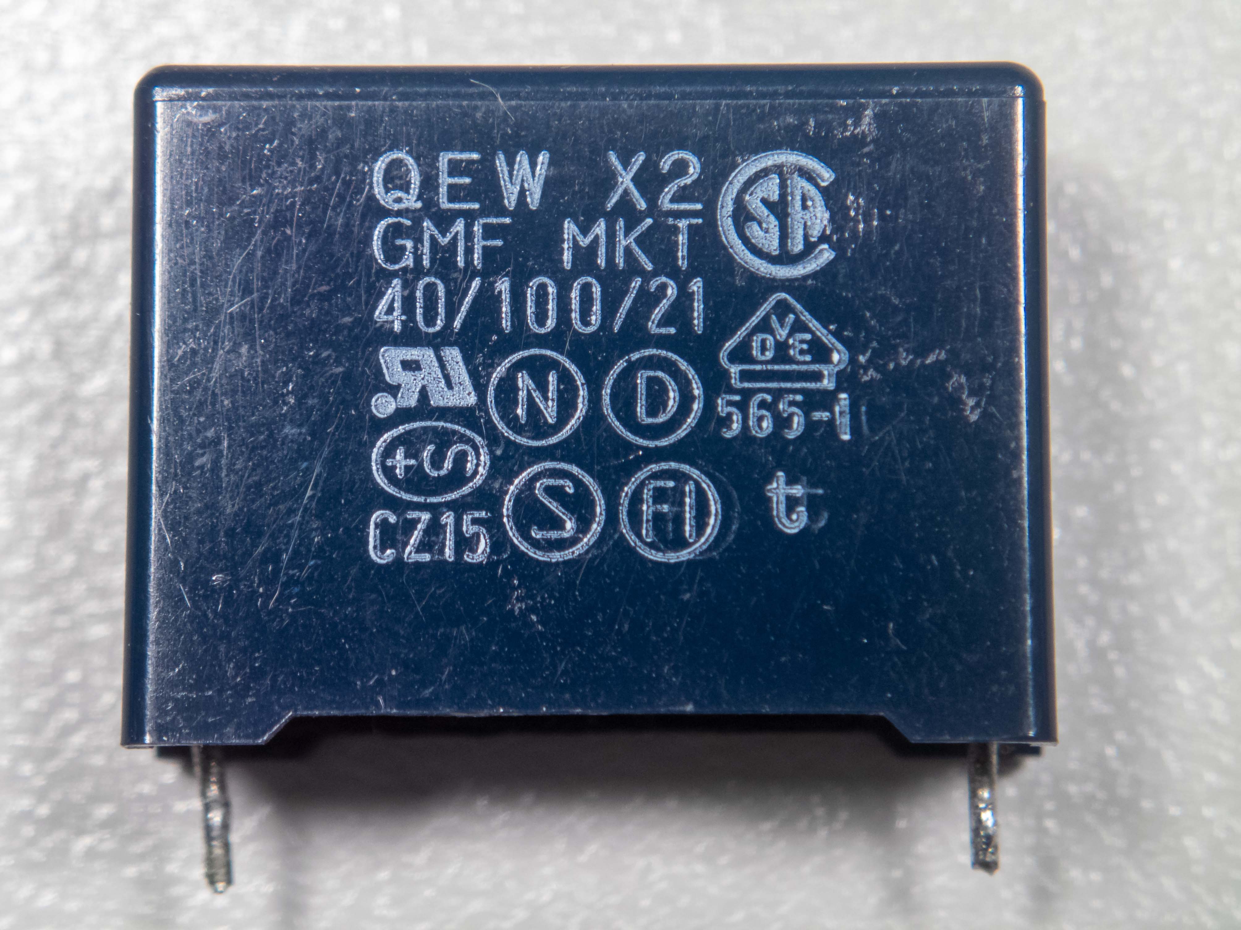
The reason mains-connected capacitors are dangerous is that they sit permanently across live wiring, so any failure mode of the part becomes a failure mode of the equipment’s safety. The whole point of the X and Y classification is to guarantee that a capacitor’s death cannot kill or shock the user — which, given the self-healing behavior described earlier, is precisely why safety capacitors are built from self-healing metallized film (polypropylene for X2 and the better parts, sometimes metallized paper in older designs). A metallized film part fails open, and open is the safe direction.
7.5.1 Class X: across the line
A Class X capacitor is connected line-to-line — across the mains, between live and neutral. Its job is EMI suppression: shunting high-frequency noise so it neither escapes the equipment nor enters it. The safety logic of class X is that a short-circuit failure here connects live to neutral, which the building’s fuse or breaker will clear — it will not directly shock the user, though it may cause overheating or fire if the part fails badly. So the danger a class-X part must guard against is fire, and the requirement is that it survive the surges that appear across the mains without a destructive failure. Class X is subdivided by how big a surge it must take:
- X1 — the heavy-duty grade, rated for peak impulse voltages above 2.5 kV and up to 4 kV, for installations exposed to large surges.
- X2 — the general-purpose grade, rated to a 2.5 kV peak impulse, and by far the most common; the boxed 275 VAC or 305 VAC “across-the-line” cap in nearly every switch-mode supply and appliance input filter is an X2.
- X3 — a lighter grade rated to 1.2 kV, for less demanding domestic use.
7.5.2 Class Y: line to ground
A Class Y capacitor is connected line-to-ground — between a live conductor and the chassis or protective earth, bridging what is otherwise an insulation barrier. This is the more dangerous position, because if a Y capacitor fails short, it connects the mains directly to the metalwork the user touches: a potential electrocution. Class-Y parts therefore carry a stricter requirement. They must fail open under all circumstances, they must withstand much higher surge voltages, and they are built and tested to bridge a safety insulation barrier (basic, supplementary, double, or reinforced insulation). The subclasses track the insulation they replace and the surge they take:
- Y1 — the most robust, rated to withstand an 8 kV peak impulse, suitable for bridging reinforced or double insulation, typically at line voltages up to 250 VAC.
- Y2 — the common grade, rated to a 5 kV peak impulse, for basic or supplementary insulation at roughly 150–300 VAC; the small blue or brown disc-or-box cap from live to earth in an appliance is usually a Y2.
- Y3 and Y4 — lighter grades for lower voltages and surges.
7.5.3 Why they must never be substituted
The single most important bench rule about safety capacitors is that they are not interchangeable with ordinary capacitors, and never with each other in the wrong direction. An ordinary film or ceramic cap of the same value and voltage rating may look identical, but it has not been designed or agency-tested to fail safely, and it may fail short — the one thing a mains-connected part must never do. A safety capacitor must carry the genuine approval marks of the safety agencies (VDE, UL, ENEC and the like) printed on its body, and a repair that replaces one with an unrated part, or drops a mere X-rated part into a Y position, has quietly removed a safety barrier the equipment was certified to have. In restoration and repair this is the one place where “it’s just a capacitor” is actively wrong.
7.5.4 The classic slow death of cheap X2 caps
Safety capacitors are also the film cap with the best-documented wear-out failure, and it is worth knowing because it is so common. Cheap X2 metallized-polypropylene suppression caps, sitting across the mains for years, slowly admit moisture through their casing. The water reaches the exposed edges of the metallization and, aided by the constant AC field, corrodes it — the same electrode that self-healing relies on. The capacitance quietly falls, the part’s noise-suppression job degrades, and in bad cases the casing cracks and the cap can smell, smoke, or char. A failed suppression cap that no longer does its job is a frequent cause of a device that “still works but now interferes with the radio,” and a cracked, browned X2 across the mains is a routine find in aging switch-mode supplies. Better parts use improved encapsulation and metallization to resist exactly this, which is part of what the price difference buys.
7.6 Ratings that matter for film
A film capacitor’s datasheet carries a few parameters that catch out engineers used to ceramics and electrolytics, all of them consequences of the fact that film caps are frequently asked to pass real AC and pulse current rather than merely decouple.
AC voltage is not DC voltage. A film cap rated 630 V DC is not rated to sit across 630 V AC. Under AC the dielectric sees the full peak of the waveform every half-cycle, the losses generate continuous heat, and — the killer — the internal field stress and the electrode current are far more punishing than under a static DC bias. AC-rated parts carry a separate, much lower AC voltage rating, and using a DC-rated cap on AC without heavy derating is a classic way to cook one.
dV/dt and pulse handling. For snubbers and other pulse duty the limiting number is often not voltage at all but dV/dt, the maximum rate of voltage change the part can take. A steep edge drives a large current (I = C · dV/dt) through the electrode and, especially, through the thin end-connection where the metallization meets the terminal. Exceed the rating and that contact overheats and degrades. Film/foil construction, with its solid electrode and robust connection, tolerates far higher dV/dt than metallized film, which is why the highest-pulse snubber parts are film/foil polypropylene.
Self-heating and frequency derating. Because a film cap under AC dissipates real power in its ESR, it heats itself, and its permissible AC voltage therefore falls as frequency rises — more cycles per second means more loss events per second means more heat. Every AC film datasheet includes a curve of allowable AC voltage versus frequency, and ignoring it is how a nicely specified cap ends up running hot enough to soften its own dielectric. This is the flip side of polypropylene’s low loss: it is precisely because PP dissipates so little that it, and not polyester, is the film that can be pushed hard on AC.
7.7 Where film wins, and where it loses
It helps to end with the honest accounting an engineer does at selection time, and this is developed further in the selection volume.
Film wins on stability — value that holds across voltage, temperature, and time, with none of the DC-bias collapse of Class II ceramic or the drift and drying of electrolytics. It wins on low loss and low dielectric absorption, making it the choice for timing, integration, filters, and precision analog. It wins on AC and pulse capability, handling current and dV/dt that would destroy other types. It wins on self-healing, which gives it graceful failure and makes it the only safe choice for mains-connected duty. And it wins on longevity: with no electrolyte to dry out and no polarity to violate, a film cap simply lasts.
Film loses on size and cost per microfarad. A ceramic chip of the same capacitance is a fraction of the volume and a fraction of the price; an electrolytic buys capacitance by the thousand-microfarad for pennies. Film cannot reach the bulk capacitance an electrolytic delivers — the practical range runs from a few picofarads up to some tens of microfarads, and the large end is already physically imposing. So the film capacitor is never the answer for bulk energy storage, reservoir smoothing, or dense decoupling. It is the answer when the quality of the capacitance matters more than the quantity — and in the analog, power, and safety corners of electronics, it very often does.
7.8 Practical notes for the bench
A few closing observations that come up whenever film caps are actually in hand.
Film capacitors nearly always wear their values printed in plain text rather than in the colored bands or dot codes of older parts — a value, a tolerance letter, a voltage, and (for mains parts) the class and agency marks. The reading conventions, including the three-digit picofarad code that appears on the smaller ones, are covered in the reading-a-capacitor volume. The dielectric is frequently identifiable from the type code on the body: an MK-prefix means metallized (MKT polyester, MKP polypropylene), while a bare K-prefix (KP, KS, FKP) signals film/foil.
Because film caps are non-polar, stable, and low-leakage, they are the safe modern replacement for the old paper capacitors whose failure modes make vintage restoration such an adventure — the direct successor covered in the paper-capacitor volume. Dropping a modern polyester or polypropylene part into the socket of a leaking waxed-paper cap restores the original circuit with a component that will not develop the DC leakage that destroys output transformers and shifts bias points. The one thing to respect in that swap is voltage rating and, if the original sat across the mains, its safety class: replace an across-the-line cap only with a properly X- or Y-rated part.
And finally, the family’s reputation for quality is earned but not magical. A film capacitor is stable, low-loss, self-healing, and long-lived because its plastic dielectric is genuinely well-behaved — but it is still a real component with ESR, ESL, a self-resonant frequency, and dielectric absorption, all of them small but not zero, and all of them treated in the real-capacitor and measurement volumes. The film cap is the quality capacitor of the analog world precisely because those imperfections are as small as any technology makes them — not because they are absent.
Comments (0)