Capacitors · Volume 5
Reading a Capacitor: Markings, Codes, and the Old Colored Dots
5.1 Why a capacitor is so hard to read
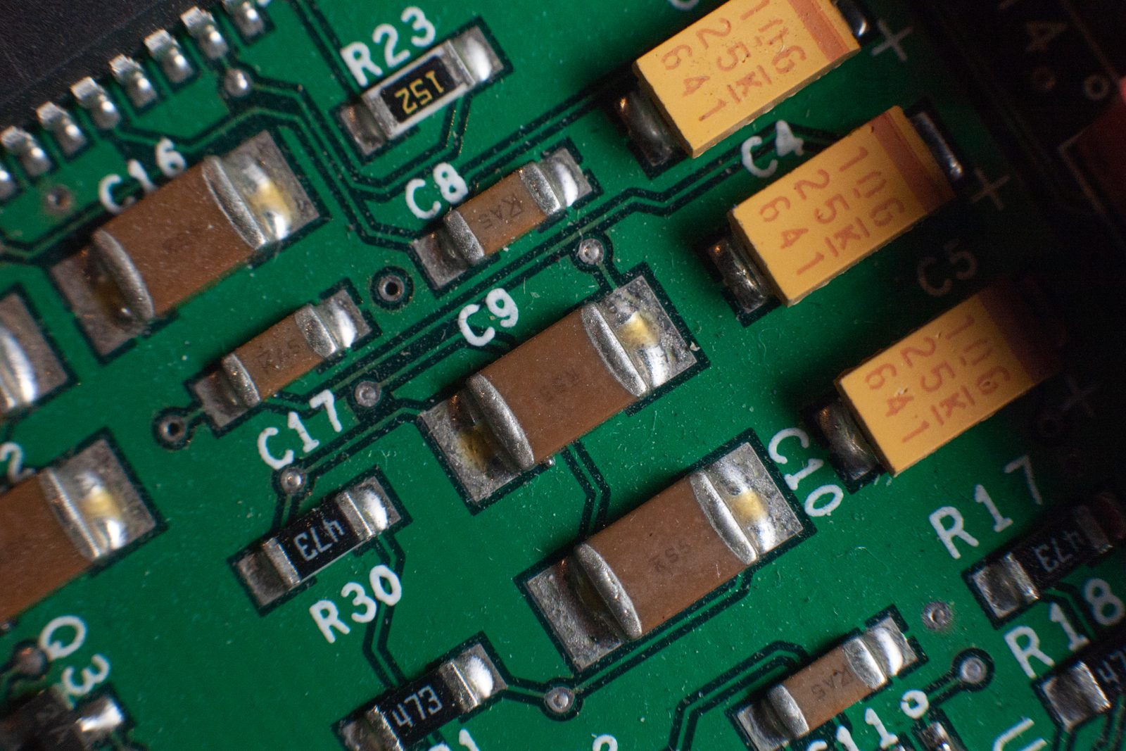
A resistor tells you almost everything with four colored bands and a decimal point. A capacitor is not so tidy. The same value can be printed as 0.1, 100n, 104, .1 MFD, or 100000 depending on the decade, the country, and the mood of the factory. A part the size of a grain of rice may carry no marking at all, while a molded rectangle from 1948 carries six dots of colored paint and expects the reader to know which corner to start at. Between those extremes lies a century of overlapping, half-abandoned conventions, several of which still turn up on the same workbench in the same afternoon.
This volume is the decoder ring. The goal is narrow and practical: to make any capacitor marking readable, whether it is a laser-etched code on a modern multilayer chip or a faded dot on a capacitor pulled from a 1937 console radio. What the codes mean physically — why a part is C0G rather than X7R, why an old paper capacitor with a perfectly legible value is nonetheless junk — belongs to the technology volumes; this one is about turning ink and paint back into numbers.
Two readers should leave satisfied. The person recapping a vintage receiver needs to look at a wax-dipped tubular with three colored bands and know what to order as a replacement. The engineer staring at a reel of 0402 chips needs to know that the absence of a marking is itself information, and how to reconstruct the part number from the reel label. Both are reading the same four or five facts; they are just encoded differently.
5.2 The four facts a marking must carry
Strip away the formats and every capacitor marking is trying to communicate the same short list. In rough order of importance:
- Capacitance — the value, in farads, though almost always expressed in microfarads (µF), nanofarads (nF), or picofarads (pF).
- Rated voltage — the maximum DC working voltage. Ignore this and the part fails, sometimes spectacularly.
- Tolerance — how far the real value may stray from the marked one, as a percentage or an absolute picofarad figure.
- Dielectric / temperature characteristic — what the capacitor is made of and how its value drifts with temperature (C0G, X7R, a film-type letter). Often a single code that implies both.
Two more facts appear when they matter: polarity, on electrolytics and tantalums, where connecting it backwards is a genuine hazard; and a date or lot code, which the manufacturer cares about for traceability and which the restorer cares about because a capacitor’s age is a clue to whether it can be trusted. The manufacturer’s name or logo rounds out the set.
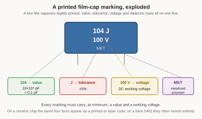
Not every marking carries all of these. A bare 0402 chip carries none — the value lives only on the reel. A big electrolytic can spell out everything in plain text. Most parts sit in between, compressing the value and tolerance into a code and printing the voltage where there is room. The encodings follow, from the ones that spell it out to the ones that hide it in paint.
5.3 When the value is simply printed
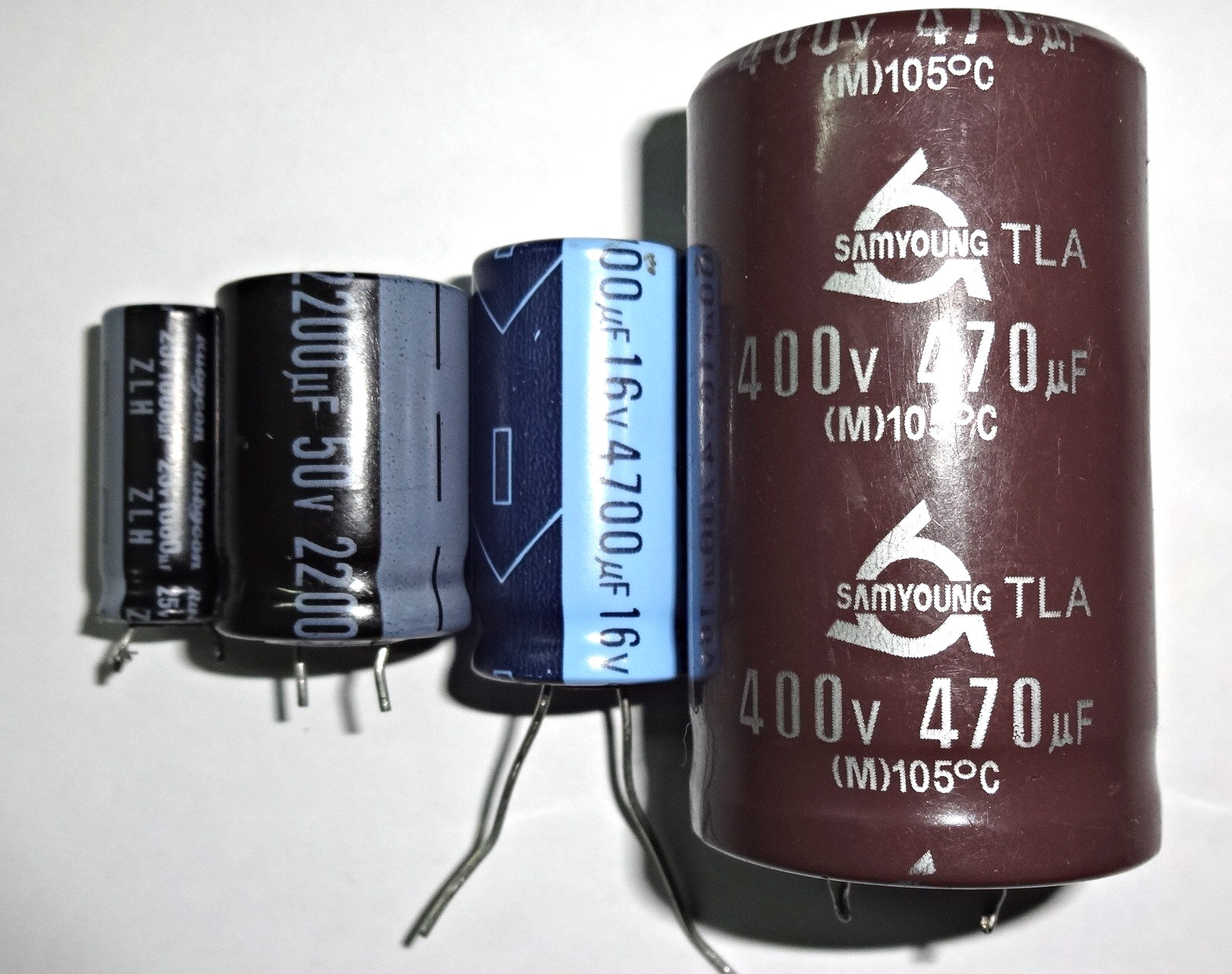
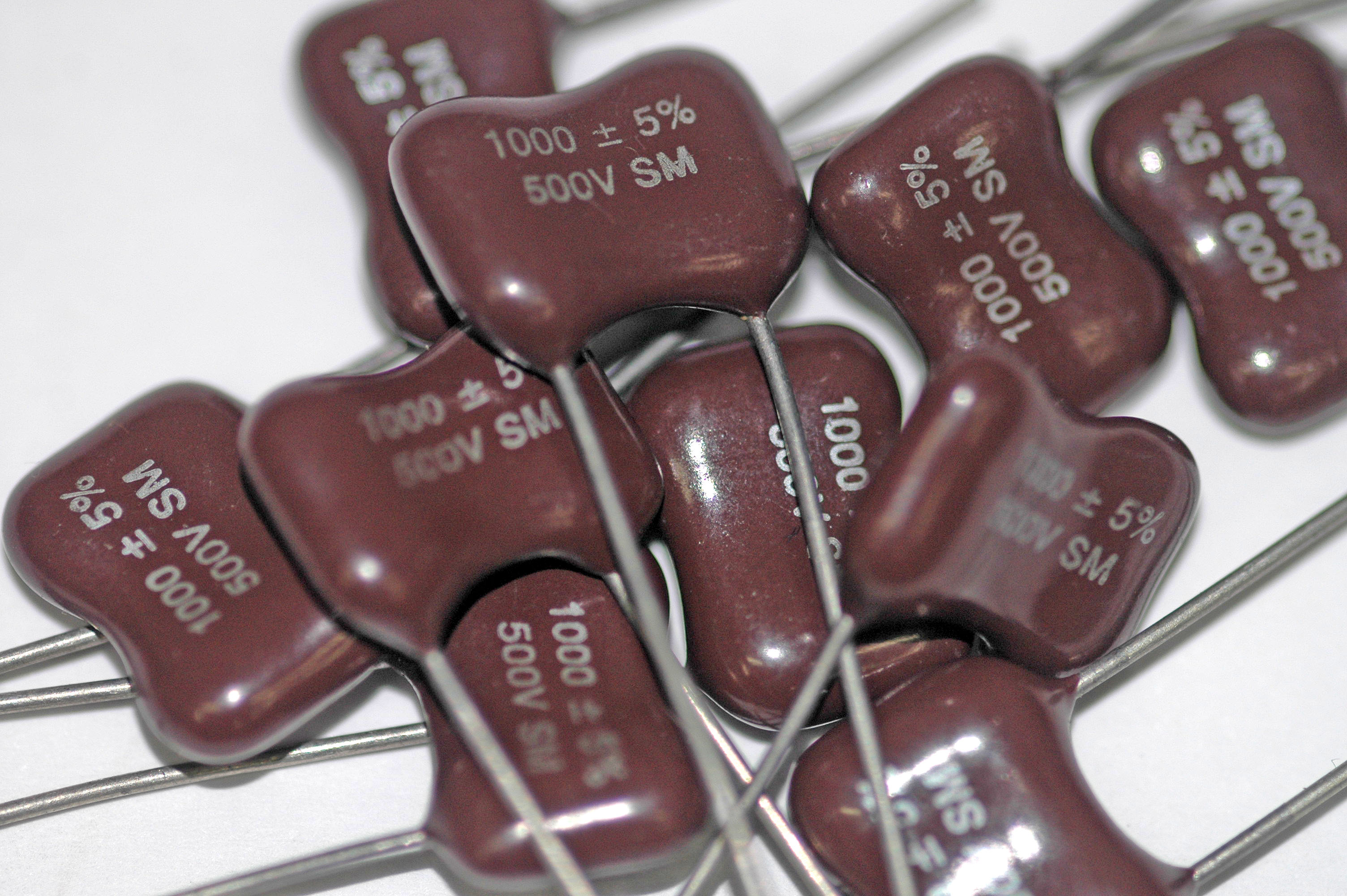
The friendliest markings state the value outright, and they appear on the parts big enough to hold text: aluminum electrolytics, large film boxes, and modern MLCCs in the bigger case sizes. An electrolytic can that reads 47µF 25V is telling the truth in full. A film box that reads 0.22 250 is a 0.22 µF part rated 250 V. There is little to decode — but there is a historical trap in the units themselves, and it has ruined more than one restoration.
5.3.1 The µF / MFD / mmfd swamp
The microfarad is written a dozen ways, and older gear treated the notation casually. On a mid-century American schematic or capacitor, one routinely finds:
Table 1 — The microfarad is written a dozen ways, and older gear treated the notation casually. On a mid-century American schematic or capacitor, one routinely finds
| Written as | Means | In modern units |
|---|---|---|
| µF, uF, mF, MF, MFD, mfd | microfarad | 1 µF = 10⁻⁶ F |
| mmF, mmfd, µµF, MMFD, pfd | picofarad | 1 pF = 10⁻¹² F |
The killer is the second row. Before “pico” and “nano” entered common shop use in the 1960s, the picofarad was written as the micro-microfarad — µµF, or in typewriter-friendly form mmfd. So a capacitor marked 250 mmfd is 250 pF, not 250 nF and certainly not 250 µF. The lowercase mfd almost always meant microfarad; the doubled mmfd meant micro-microfarad, i.e. picofarad. To make it worse, mF today formally means millifarad (10⁻³ F), a unit that scarcely appears on discrete parts but shows up on supercapacitors and in SPICE netlists. When reading a vintage schematic the safe habit is: a doubled prefix (mmfd, µµF) is picofarads; a single mfd/MFD is microfarads; and if a value looks absurd by a factor of a million, the units notation is the reason.
There is no nanofarad in classic American practice at all — values that a European would call 10 nF were written 0.01 µF or 10,000 mmfd. Nanofarads were, and to some extent remain, a European and hobbyist convention. This is why 100n, 0.1 µF, 104, and 100000 pF are four spellings of one capacitor.
5.4 The three-digit numeric code
The workhorse of small ceramic and film capacitors is a compact three-digit code, borrowed straight from the resistor world: two significant figures followed by a power-of-ten multiplier, and the answer is always in picofarads. A part marked 104 is not 104 of anything. It is 10, followed by four zeros: 10 × 10⁴ = 100 000 pF = 100 nF = 0.1 µF.
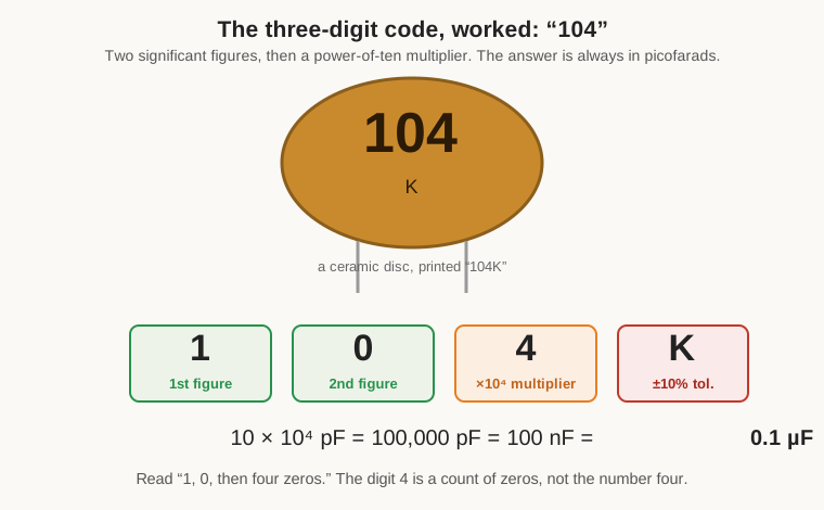
The multiplier digit is a count of zeros, not a coefficient. Some worked examples cover the common ground:
Table 2 — The multiplier digit is a count of zeros, not a coefficient. Some worked examples cover the common ground
| Code | Reads as | Picofarads | Convenient form |
|---|---|---|---|
| 100 | 10 × 10⁰ | 10 pF | 10 pF |
| 101 | 10 × 10¹ | 100 pF | 100 pF |
| 221 | 22 × 10¹ | 220 pF | 220 pF |
| 471 | 47 × 10¹ | 470 pF | 470 pF |
| 102 | 10 × 10² | 1 000 pF | 1 nF |
| 223 | 22 × 10³ | 22 000 pF | 22 nF |
| 104 | 10 × 10⁴ | 100 000 pF | 0.1 µF |
| 474 | 47 × 10⁴ | 470 000 pF | 0.47 µF |
| 105 | 10 × 10⁵ | 1 000 000 pF | 1 µF |
| 475 | 47 × 10⁵ | 4 700 000 pF | 4.7 µF |
Two conventions extend the scheme to small values. A multiplier of 8 or 9 means a fractional multiplier — ×0.01 and ×0.1 respectively — so 339 is 33 × 0.1 = 3.3 pF and 479 is 4.7 pF. More commonly, capacitors below 10 pF use the letter R as a decimal point: 4R7 is 4.7 pF, 1R5 is 1.5 pF, 0R5 is 0.5 pF. And the smallest, simplest parts skip the code entirely and print a bare number: a disc marked just 47 is almost certainly 47 pF, and one marked .001 is 0.001 µF = 1 nF. When a lone number could be read either as a direct picofarad value or as a three-digit code, physical size and context decide — a code of 220 on a tiny chip is far more likely 22 pF (a genuine three-digit code, 22 × 10⁰) only if a decimal reading makes no sense; a disc stamped 220 is usually 22 pF as a code but occasionally a plain 220 pF. When it is ambiguous, measure it.
5.5 Tolerance: the trailing letter
Directly after the value, printed or coded, comes a single letter giving the tolerance. This letter system is defined by the EIA (the Electronic Industries Alliance, successor to the RMA and RETMA trade groups whose initials still haunt old datasheets) and is nearly universal:
Table 3 — Directly after the value, printed or coded, comes a single letter giving the tolerance. This letter system is defined by the EIA (the Electronic Industries Alliance, successor to the RMA and RETMA trade groups whose initials still haunt old datasheets) and is nearly universal
| Letter | Tolerance (≥ 10 pF) | Letter | Tolerance (< 10 pF, absolute) |
|---|---|---|---|
| F | ±1% | B | ±0.1 pF |
| G | ±2% | C | ±0.25 pF |
| H | ±3% | D | ±0.5 pF |
| J | ±5% | F | ±1 pF |
| K | ±10% | G | ±2 pF |
| M | ±20% | — | — |
| Z | +80% / −20% | P | +100% / −0% |
The split matters. For capacitances of 10 pF and up, the letters denote a percentage; for tiny capacitances where 1% would be meaningless, the same letters (B, C, D, and reused F, G) denote an absolute picofarad window. So 100D on a 10 pF part means ±0.5 pF, while 104J on a 0.1 µF part means ±5%. The very loose codes belong to the high-permittivity ceramics: Z, meaning +80%/−20%, is the calling card of a Y5V or Z5U decoupling capacitor whose actual capacitance is more of a suggestion than a specification. The very tight codes — B, C, D, F — belong to Class 1 ceramics, mica, and film, where the value is a design parameter and not merely a bypass.
Which caps get which tolerance follows the job. A timing or filter capacitor that sets a frequency wants F, G, or J and a stable dielectric; a bulk-decoupling capacitor whose only duty is to be “big enough” happily wears K, M, or Z. Reading the tolerance letter therefore also hints at what the part was for.
5.6 Voltage: printed, or coded in a letter and a number
Working voltage is stated in plain text wherever the part is large enough — 50V, 250, 1kV. On small chips and in coded part numbers it is compressed into the EIA voltage code, a letter followed by a digit, where the letter is a two-figure mantissa and the digit is the number of zeros:
Table 4 — Working voltage is stated in plain text wherever the part is large enough — 50V, 250, 1kV. On small chips and in coded part numbers it is compressed into the EIA voltage code, a letter followed by a digit, where the letter is a two-figure mantissa and the digit is the number of zeros
| Mantissa letter | A | C | E | G | H | J |
|---|---|---|---|---|---|---|
| Value | 1.0 | 1.6 | 2.5 | 4.0 | 5.0 | 6.3 |
Multiply by 10ⁿ where n is the trailing digit. The common results:
Table 5 — Multiply by 10ⁿ where n is the trailing digit. The common results
| Code | Value | Code | Value |
|---|---|---|---|
| 1A | 10 V | 2A | 100 V |
| 1C | 16 V | 2D | 200 V |
| 1E | 25 V | 2G | 400 V |
| 1H | 50 V | 2J | 630 V |
| 1J | 63 V | 3A | 1000 V |
So 1E is 2.5 × 10 = 25 V and 2J is 6.3 × 100 = 630 V. A parallel, simpler single-letter system appears mostly on SMD electrolytics and tantalums — for example e = 2.5 V, G = 4 V, J = 6.3 V, A = 10 V, C = 16 V, E = 25 V, V = 35 V, H = 50 V — but these single-letter tables are manufacturer-specific and must be checked against the maker’s datasheet rather than assumed. The reason to bother with any of this is unforgiving: a capacitor run near or above its rated voltage loses life fast and, in the case of electrolytics and ceramics, can fail short. The voltage rating is not optional trivia; it is a limit.
5.7 The dielectric code, as a marking
Ceramics carry a two- or three-character dielectric code that doubles as a temperature-characteristic specification. On the bench it is read as an identity — “that’s a C0G, that’s an X7R” — and its full behavior is decoded in the ceramic volume. For recognition, two families matter.
Class 1 (stable, low-loss, for timing and RF) uses the EIA three-character system where the characters encode the temperature coefficient in parts per million per degree Celsius:
Table 6 — Class 1 (stable, low-loss, for timing and RF) uses the EIA three-character system where the characters encode the temperature coefficient in parts per million per degree Celsius
| EIA code | Industry name | Temp. coefficient |
|---|---|---|
| C0G | NP0 | 0 ± 30 ppm/°C |
| U1G | N075 | −75 ppm/°C |
| P2H | N150 | −150 ppm/°C |
| S2H | N330 | −330 ppm/°C |
| U2J | N750 | −750 ppm/°C |
C0G and the older NP0 (“negative-positive-zero”) are the same thing: essentially zero drift. Class 2 (high permittivity, for decoupling) uses a different three-character grammar — a low-temperature letter, a high-temperature digit, and a capacitance-change letter:
Table 7 — C0G and the older NP0 ("negative-positive-zero") are the same thing: essentially zero drift. Class 2 (high permittivity, for decoupling) uses a different three-character grammar — a low-temperature letter, a high-temperature digit, and a capacitance-change letter
| 1st char (low temp) | 2nd char (high temp) | 3rd char (max ΔC) |
|---|---|---|
| X = −55 °C | 5 = +85 °C | R = ±15% |
| Y = −30 °C | 6 = +105 °C | S = ±22% |
| Z = +10 °C | 7 = +125 °C | V = +22 / −82% |
So X7R survives −55 to +125 °C with no more than ±15% change, and Y5V covers −30 to +85 °C but may lose up to 82% of its value across that range. The reader needs only to recognize the format here; the ceramic volume explains why an X7R’s marked value and its in-circuit value can be very different things. Film capacitors carry their own type letters — MKT and MKP for metallized polyester and polypropylene, KP and KS for film-foil types — printed rather than coded, and covered in the film volume.
5.8 The colored dots and bands
For a stretch running from the 1920s into the 1960s, capacitors were marked exactly as resistors were: with colored paint. The scheme reached its fullest form on molded-mica capacitors — the flat brown or black rectangles that collectors call “postage-stamp” micas — and appeared in a simpler form on tubular ceramics and on some wax-dipped paper capacitors. Reading them is the reason this volume exists, because the color paint has often faded, the standards changed twice, and the same six dots meant different things in 1938, 1948, and 1958.
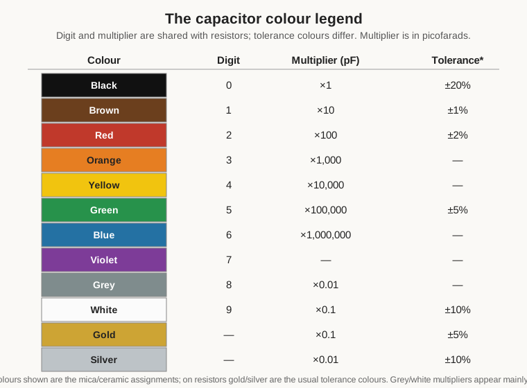
The color-to-number legend is shared with resistors and shown in Figure 4: black 0, brown 1, red 2, orange 3, yellow 4, green 5, blue 6, violet 7, grey 8, white 9. The multipliers follow the same colors as powers of ten (in picofarads), and gold/silver serve as fractional multipliers and tolerance markers. What changes between systems is not the legend but the layout — which dot is read first, in which direction, and what each position encodes.
5.8.1 The six-dot molded-mica code
The definitive form is the EIA six-dot code on molded-mica postage stamps. Six paint dots sit in two rows of three. The part is read clockwise starting at the top-left dot, and an arrow molded or printed into the case usually points the way. The first dot is not a value at all — it is a flag identifying which standard is in force:
- White top-left dot → the current EIA code (post-1948).
- Black top-left dot → the military / JAN code (the RMA/RETMA-derived MIL standard), which uses the same layout.
- Silver top-left dot → the part is a paper capacitor, not mica, using the same dot grammar.
- A colored (digit) top-left dot → the older RMA/RETMA code, in which there is no flag and all three top dots are read as significant figures or figure-figure-multiplier.
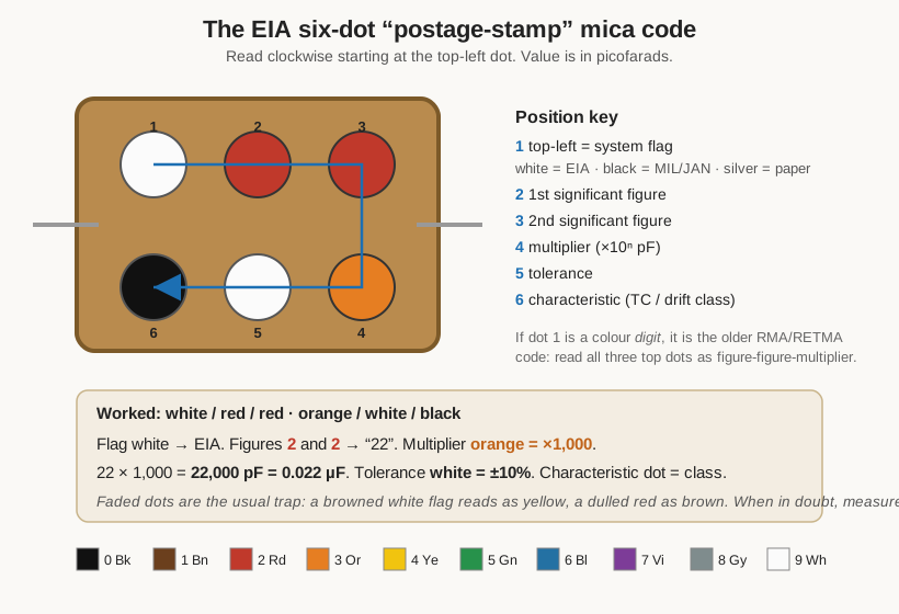
In the EIA six-dot layout, the six positions read as follows:
Table 8 — In the EIA six-dot layout, the six positions read as follows
| Position | Dot | Meaning |
|---|---|---|
| Top-left | 1 | System flag (white = EIA) |
| Top-middle | 2 | First significant figure |
| Top-right | 3 | Second significant figure |
| Bottom-right | 4 | Decimal multiplier (× 10ⁿ pF) |
| Bottom-middle | 5 | Tolerance |
| Bottom-left | 6 | Characteristic (temperature coefficient / drift class) |
A worked example: white / red / red across the top, then orange / white / black around the bottom. The white flag says EIA. The two reds give figures 2 and 2, so “22.” The bottom-right orange is the multiplier, ×1 000. That is 22 × 1 000 = 22 000 pF = 0.022 µF. The bottom-middle white is the tolerance, ±10%. The bottom-left dot is the characteristic, a class letter (typically C, D, E, or F) that specifies the temperature coefficient and maximum capacitance drift — the mica equivalent of the ceramic C0G/X7R code:
Table 9 — A worked example: white / red / red across the top, then orange / white / black around the bottom. The white flag says EIA. The two reds give figures 2 and 2, so "22." The bottom-right orange is the multiplier, ×1 000. That is 22 × 1 000 = 22 000 pF = 0.022 µF. The bottom-middle white is the tolerance, ±10%. The bottom-left dot is the characteristic, a class letter (typically C, D, E, or F) that specifies the temperature coefficient and maximum capacitance drift — the mica equivalent of the ceramic C0G/X7R code
| Characteristic | Temp. coefficient | Max. capacitance drift |
|---|---|---|
| C | −200 to +200 ppm/°C | ±(0.5% + 0.1 pF) |
| E | −20 to +100 ppm/°C | ±(0.1% + 0.1 pF) |
| F | 0 to +70 ppm/°C | ±(0.05% + 0.1 pF) |
The three-dot code is the same idea stripped to essentials: three dots, read left to right, giving first figure, second figure, and multiplier, with the tolerance fixed at ±20% and the voltage at 500 V understood by omission. It appears on the smallest, cheapest micas. A five-dot variant inserts a voltage dot. And the older pre-EIA RMA/RETMA six-dot code — the one with a colored top-left dot rather than a white or black flag — reads the top row as figures and the bottom row (right to left) as multiplier, voltage, and tolerance, a genuinely different assignment that is the main reason two collectors can decode the same capacitor and disagree. When the top-left dot is a color, assume the old system and cross-check by measuring.
5.8.2 The tubular ceramic band code
Tubular ceramic capacitors — the small cylindrical parts common in valve-era radios and early transistor gear — used a color-band scheme read from one end, much like a resistor but with an extra wrinkle at the front. The distinctive feature is a wide first band giving the temperature coefficient, followed by two significant-figure bands, a multiplier band, and a tolerance band.
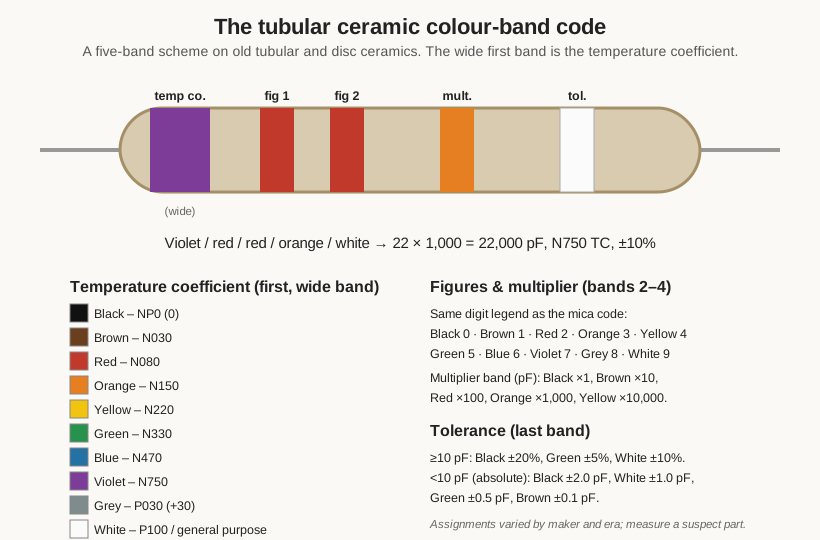
The temperature-coefficient band uses its own color assignment, expressed in the “N-number” notation (N750 meaning −750 ppm/°C, P100 meaning +100 ppm/°C):
Table 10 — The temperature-coefficient band uses its own color assignment, expressed in the "N-number" notation (N750 meaning −750 ppm/°C, P100 meaning +100 ppm/°C)
| Color | Temp. coefficient | Color | Temp. coefficient |
|---|---|---|---|
| Black | NP0 (0) | Blue | N470 |
| Brown | N030 | Violet | N750 |
| Red | N080 | Grey | P030 (+30) |
| Orange | N150 | White | P100 / general purpose |
| Yellow | N220 | ||
| Green | N330 |
The two figure bands and the multiplier band use the standard digit legend from Figure 4, in picofarads. The tolerance band splits the same way the tolerance letters do: for values of 10 pF and up it is a percentage (black ±20%, green ±5%, white ±10%), while for values under 10 pF it is an absolute figure (black ±2.0 pF, white ±1.0 pF, green ±0.5 pF, brown ±0.1 pF). A part banded violet / red / red / orange / white therefore reads: N750 temperature coefficient, figures 2 and 2, multiplier ×1 000, tolerance ±10% — a 22 000 pF, N750 ceramic. These assignments drifted between manufacturers and eras, and this same banding was applied to some ceramic disc capacitors into the 1960s where it is easily confused with later printed markings, so a measured check on any suspect tubular is time well spent.
Older wax-and-paper tubulars sometimes carried a related but cruder scheme — a body color plus one or two dots or a single band — where the body tint and dot together encoded value and a temperature or voltage class. These body-tint systems were never as standardized as the mica dots, and the wisest course with any color-marked paper capacitor is to read it for a starting value and then replace it outright; the paper-capacitor volume explains why almost all of them are electrically suspect regardless of what the paint claims.
5.9 Date and lot codes
Somewhere on a well-marked capacitor, often on a second printed line, sits a date code — the manufacturer’s traceability stamp, and to a restorer a rough birth certificate. The dominant modern form is a four-digit YYWW code: the first two digits are the year, the last two the week of manufacture. 2314 is the 14th week of 2023. Older parts, and some military ones, use an EIA date code in which a letter or digit encodes the year (cycling through the alphabet, skipping the ambiguous letters) and a following character encodes the month, with October, November, and December often given as O/N/D or as X/Y/Z to keep them to one character. Because these letter systems repeat and vary between makers, a date code is best treated as corroboration rather than proof — but it earns its keep. An aluminum electrolytic’s usefulness is bounded by its age even if it has never been powered; a date code from the 1980s on a filter capacitor is, by itself, an argument for replacement.
5.10 Polarity: the stripe that means the opposite thing
Electrolytic and tantalum capacitors are polarized — they have a right way round, and installing one backwards ranges from disappointing to violent. The marking that indicates polarity is where an otherwise careful builder gets caught, because the two dominant families mark opposite terminals.
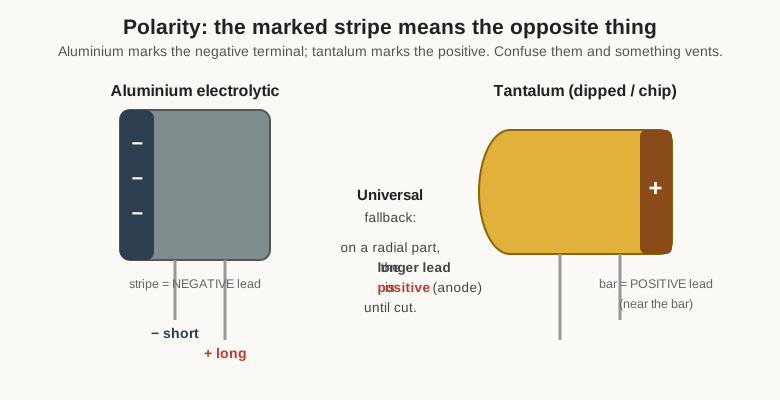
On an aluminum electrolytic, the printed stripe down the side of the can — usually filled with minus signs, sometimes an arrow — marks the negative terminal. On a tantalum capacitor, the bar or stripe marks the positive terminal. Same visual cue, opposite meaning. The mnemonic worth keeping is simply “aluminum marks the minus, tantalum marks the plus,” because reversing a tantalum in particular tends to end in fire. Two further conventions help: on a fresh radial part with unequal leads, the longer lead is positive (the anode) until someone trims it; and on surface-mount electrolytics and tantalum chips, a printed bar at one end marks that end’s polarity per the family rule — negative for the aluminum SMD can, positive for the tantalum chip. When in doubt and the part is in circuit, the pad connected to the more-positive rail is the anode, and a meter settles it.
5.11 Putting it together: three identifications
Theory assembled, here are three real parts decoded end to end — one modern, one mid-century, one older still.
A modern 0805 MLCC. The chip itself is blank; its identity lives on the cut-tape strip, whose label reads GRM21BR71H104KA01. The reader does not need the full manufacturer grammar to extract the essentials: 104 is the value (0.1 µF), K is the tolerance (±10%), 1H is the voltage code (5.0 × 10 = 50 V), and R7 in the dielectric field marks it X7R. A 0.1 µF ±10% 50 V X7R decoupling capacitor — exactly what one would expect on the power pin of a logic chip.
A 1960s postage-stamp mica. A flat brown rectangle with six dots. Top-left dot white → EIA. Top row continues brown, black → figures 1 and 0, “10.” Bottom-right (multiplier) red → ×100. That is 10 × 100 = 1 000 pF. Bottom-middle (tolerance) green → ±5%. Bottom-left (characteristic) is a class dot indicating a low-drift mica. So: 1 000 pF, ±5%, stable — a coupling or timing capacitor, and being mica, one of the few vintage parts likely to still be within spec.
A vintage tubular ceramic with color bands. A small cylinder banded, from the wide end, orange / yellow / violet / brown / green. The wide orange band is the temperature coefficient, N150. Yellow and violet are figures 4 and 7, “47.” Brown is the multiplier, ×10. That is 47 × 10 = 470 pF, tolerance green ±5%, temperature coefficient N150 — a small, mildly temperature-compensating ceramic of the kind used in oscillator and IF stages. A quick meter check confirms the reading, because a fifty-year-old paint job is not a datasheet.
5.12 When the marking lies, or has faded
The last skill of reading capacitors is knowing when to stop trusting the marking. Paint fades and shifts hue: a browned white flag dot reads as yellow, a sun-dulled red reads as brown, and a silver body oxidizes toward grey. Printed codes rub off, and laser marks on dark chips can be nearly invisible at the wrong angle. When the marking is ambiguous, the answer is not to guess harder but to reach for an LCR meter or a capacitance meter and read the value directly — the measurement volume covers how to do that without being fooled by lead length and fixture strays.
And there is a subtler failure the marking cannot warn you about: a capacitor whose printed value is perfectly correct and perfectly irrelevant, because the dielectric underneath has degraded. An old wax-paper capacitor may still measure close to its marked capacitance on a meter while leaking current badly under working voltage; a tantalum may read fine until the instant it shorts. The marking describes what the part was built to be, not what it has become. For the families where this matters most — paper and old electrolytics above all — the correct reading of a marking is sometimes “replace it,” and the paper-capacitor and electrolytic volumes make the case for why. A marking tells you what to order. It does not tell you what to keep.
Comments (0)