Capacitors · Volume 9
Tantalum and Niobium Capacitors: Density, Derating, and the Ignition Failure
9.1 The most and least forgiving capacitor at once
There is a family of capacitors that packs more capacitance into a given volume than almost anything else a designer can solder to a board, holds that capacitance rock-steady as the voltage and temperature swing, never dries out, and comes in flat little chips that hide under a connector. There is also a family of capacitors with a reputation for bursting into flame. These are the same family. The tantalum capacitor is simultaneously one of the most useful and one of the most feared parts in the passives cabinet, and understanding why both things are true at once is the whole of this volume.
The reputation is not folklore. A solid tantalum capacitor, mistreated, does not merely fail — it can ignite, flare, and short the rail it was decoupling, occasionally with a small jet of flame and a puff of acrid smoke. Generations of engineers have watched a prototype’s tantalum go up on first power-on and learned the lesson the hard way. And yet the same part, treated with the respect its datasheet demands, will outlast the product it lives in, sitting quietly under a processor providing a stability of capacitance that a multilayer ceramic (MLCC) simply cannot match. The gap between those two outcomes is a body of doctrine — voltage derating, inrush limiting, polarity discipline, and the newer chemistries that soften the failure — and that doctrine is what separates an engineer who uses tantalums from one who is afraid of them.
Tantalum belongs to the same broad category as the aluminum electrolytic covered in its own volume: both are electrolytic capacitors, meaning both grow their dielectric as a thin oxide skin on a roughened metal anode, and both are polarized — they have a right way round and a fatal wrong way round. But the resemblance ends quickly. Where the aluminum type roughens a flat foil by etching and keeps a wet electrolyte sloshing against the oxide, the tantalum type builds its anode as a sintered sponge of metal powder and, in its most common form, replaces the liquid electrolyte with a solid. That single change — solid instead of wet — is the source of the tantalum’s virtues (stability, longevity, tiny size) and, through a quirk of chemistry, the source of its vice as well.
9.2 What tantalum brings to the bench
Before the failure mode steals the show, it is worth being clear about why anyone tolerates the risk. Tantalum earns its place through a cluster of properties that are hard to get together in any other single component.
The headline is volumetric efficiency — capacitance per cubic millimetre. The anode is not a flat plate but a slug of sintered tantalum powder, a rigid metallic sponge threaded with pores, and the usable electrode area is the entire internal surface of that sponge. On top of that vast area sits the dielectric, tantalum pentoxide (Ta₂O₅), grown only nanometres thick. Area times the reciprocal of thickness is capacitance, and both terms are pushed hard, so a tantalum chip the size of a grain of rice can hold tens of microfarads. Ta₂O₅ helps twice over: its relative permittivity is roughly 27, appreciably higher than aluminum oxide’s, so the same geometry yields more capacitance. The upshot, in the industry’s own terms, is that tantalum offers on the order of ten times the volumetric efficiency of aluminum oxide.
The second virtue is stability, and this is where tantalum quietly beats the ceramic capacitor at a job the ceramic is otherwise good at. A Class II ceramic — an X7R or X5R, decoded in the ceramic volume — loses a large fraction of its rated capacitance when a DC bias is applied across it; a “10 µF” X5R on a 3.3 V rail may be delivering a third of its nameplate value once biased. Tantalum does not do this. Its capacitance is essentially flat versus applied voltage and gently behaved versus temperature, so a 10 µF tantalum is 10 µF on the rail, not a hopeful label. For bulk decoupling and filtering where the actual capacitance in circuit matters — not the value on the reel — that DC-bias immunity is a genuine and underappreciated advantage.
These first two virtues are usually summarized in one figure of merit the tantalum industry lives by: the CV product, the capacitance multiplied by the rated voltage, which measures how much a given pellet can do regardless of how that capability is split between microfarads and volts. A powder grade with a high specific charge (measured in microfarad-volts per gram) lets a maker hit a target CV in a smaller pellet, and the relentless improvement of tantalum powders is most of why the parts have shrunk decade over decade while their capacitance climbed. It is also the axis along which the three cathode chemistries and the niobium alternative are compared: the wet sintered tantalum tops the CV table, the solid types follow, and niobium oxide trades a little CV for its safety and cheaper metal.
The third virtue is longevity in a low profile. Because the solid types have no liquid to lose, they do not dry out the way a wet aluminum electrolytic does; there is no rubber bung slowly outgassing, no endurance clock ticking toward an equivalent-series-resistance (ESR) cliff. And the parts are flat and light, which is why they colonized the underside of laptop and phone boards where a tall aluminum can would never fit. The modern polymer types add low and stable ESR to the list, making them credible for ripple filtering as well as bulk hold-up.
9.3 How the sponge is built
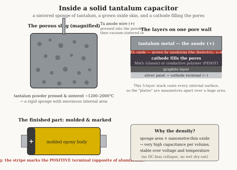
The deep process detail belongs to the manufacturing volume, but the shape of it must be sketched here because the construction is the explanation for everything that follows. The anode begins as high-purity tantalum powder, extraordinarily fine, pressed around a tantalum lead wire into a small rectangular slug. That green pellet is then vacuum-sintered — heated in vacuum to somewhere in the region of 1200–2000 °C — until the powder grains fuse to their neighbours at their contact points without melting into a solid block. What emerges is a porous, mechanically rigid sponge: a single continuous piece of tantalum riddled with an interconnected labyrinth of pores, with the anode wire fused permanently into it. The finer the powder and the gentler the sinter, the more internal surface survives, and surface is capacitance, so the powder grade is chosen to hit a target “CV” — the product of capacitance and voltage the pellet can deliver.
Next the pellet is anodized. Submerged in an electrolyte with a positive voltage applied, its entire wetted surface — the whole internal sponge — grows a conformal film of Ta₂O₅. The film’s thickness is set by the forming voltage, at roughly 1.7 nanometres of oxide per volt, so a part formed to a few hundred volts still has a dielectric only a fraction of a micron thick. This is the dielectric of the finished capacitor, and its thinness is precisely why the capacitance is so high and, later, why the voltage rating is so limited and the derating so strict: there is not much oxide standing between the plates.
Finally the cathode system is built up through the pores to make electrical contact with the oxide over that whole internal area. What the cathode is made of defines the three species of tantalum capacitor, and each deserves its own treatment. On top of the cathode proper go a graphite layer and a silver layer to collect the current out to the terminal, and the whole assembly is molded in epoxy (for chips) or dipped (for the older leaded beads) and marked.
9.4 The three cathode technologies
The oxide-coated sponge is the same in all three species; what fills its pores to make the cathode contact is what sets them apart, and the choice cascades into ESR, voltage rating, failure behaviour, cost, and application. It is worth holding the three side by side before taking each in turn. Manganese dioxide is the old solid standard — stable, cheap, proven, and flammable. Conductive polymer is the modern solid default — much lower ESR, benign failure, slightly lower voltage. Wet electrolyte is the high-reliability aristocrat — highest energy density and voltage, hermetic, expensive, and touchy about reverse bias. Nearly every tantalum decision an engineer makes is, at bottom, a choice among these three cathodes.
9.4.1 Manganese-dioxide solid tantalum: the classic, and the arsonist
The original solid tantalum, and still the workhorse of countless industrial and legacy designs, uses manganese dioxide (MnO₂) as its cathode. The porous, oxide-coated pellet is repeatedly dipped in a manganese-nitrate solution and baked, pyrolytically converting the nitrate to solid MnO₂ that penetrates the pores and coats the dielectric. MnO₂ is a semiconductor, robust, thermally stable, and it gave the world a solid electrolytic that would sit on a shelf for decades and work.
MnO₂ also has one merit that reads, in hindsight, like grim irony: a mild self-healing ability. Where a tiny flaw in the oxide leaks, the local heating converts the nearby conductive MnO₂ into a higher-resistance manganese oxide, throttling the leak and plugging the fault. This works beautifully for small defects. Its failure at large defects — and the oxygen it liberates in the process — is exactly the mechanism that makes an MnO₂ tantalum burn, and that is the subject of its own section below. For now it is enough to say: MnO₂ is the classic, it is everywhere in older and industrial gear, it is stable and cheap and proven, and it is the one that catches fire.
9.4.2 Conductive-polymer tantalum: the modern default
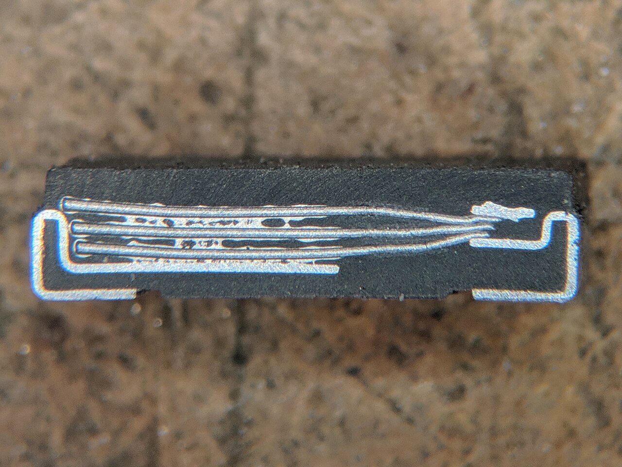
The important development of the last few decades replaces MnO₂ with a conductive polymer — typically PEDOT (poly(3,4-ethylenedioxythiophene), usually as PEDOT:PSS), an organic material that conducts electrons well and is deposited into the pellet’s pores as a slurry or polymerized in place. The polymer’s conductivity is far higher than MnO₂’s, and the payoff is a dramatic drop in ESR: a polymer tantalum can reach ESR figures a fraction of an equivalent MnO₂ part’s, which means far higher ripple-current capability and a much better job of suppressing fast transients on a rail. The polymer’s cross-section shows in Figure 3 as the dark material threaded through the tantalum sponge.
The second and arguably more important payoff is benign failure. A polymer cathode contains no reservoir of chemically bound oxygen. When a polymer tantalum is faulted past its limit, the polymer near the hot spot simply burns away — pyrolyzes — and the connection there goes open-circuit. There is no oxidizer to feed a fire, so the characteristic outcome is a localized open rather than a self-sustaining flame. This is the single biggest reason polymer tantalum has become the default choice for new low-voltage designs: it keeps most of tantalum’s virtues while removing most of its terror. The trade-offs are real but modest — polymer parts typically carry somewhat lower maximum voltage ratings than the best MnO₂ parts, tend toward higher leakage current, and the polymer can degrade thermo-oxidatively at high temperature over long life, its ESR creeping up. For the great majority of consumer and industrial rails, those are acceptable prices for not setting the board on fire.
9.4.3 Wet tantalum: the aristocrat
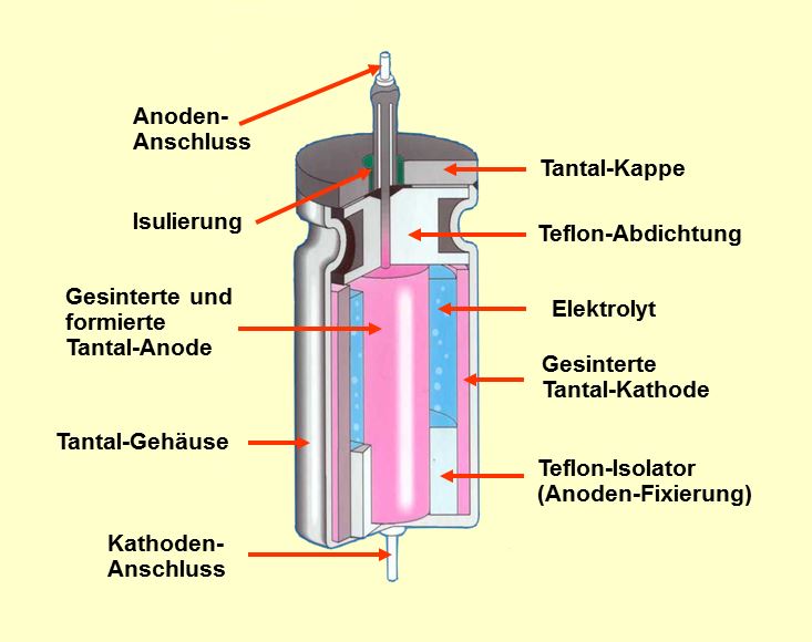
The third species keeps a liquid electrolyte and, far from being the crude old option, is the highest-performing and most expensive of all. In a wet tantalum capacitor the sintered pellet sits inside a hermetically sealed case — historically a silver can, now often an all-tantalum case for the most demanding grades — filled with a liquid electrolyte that is, in almost all designs, a strong (around 55 %) sulfuric-acid solution. Tantalum’s oxide is chemically inert enough to shrug off concentrated sulfuric acid, which is what makes such an aggressive, highly conductive electrolyte usable; the reward is a very low ESR and the ability to use the whole sponge surface as the cathode contact.
The wet sintered tantalum has the highest CV per unit volume of any polarized capacitor, and it reaches voltages the solid types cannot, with parts rated up to around 125 V in hermetic cases. It is exceptionally stable, tolerant of the environment because it is sealed, and it is the capacitor of choice where failure is not an option and money is: military and aerospace power systems, down-hole oil-and-gas instrumentation, and implantable medical devices such as pacemakers and defibrillators, where a hermetic, stable, energy-dense capacitor earns its keep. The catch — beyond cost — is a heightened sensitivity to reverse voltage: a wet tantalum tolerates even less reverse bias than a solid one before the electrolyte begins to attack the cathode side, so polarity discipline is stricter still.
9.5 Polarity: the trap that has burned a thousand engineers
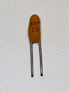
Every tantalum capacitor is polarized, and the marking convention is a genuine trap. On an aluminum electrolytic, the printed stripe marks the negative terminal — the reader who has internalized “stripe means minus” from a lifetime of aluminum cans is primed for disaster. On a tantalum, the bar, stripe, or chamfer marks the positive terminal. The conventions are opposite. A molded yellow tantalum chip with a dark band at one end is telling the assembler that the banded end is the plus; wire it as though the band were minus, as aluminum habit suggests, and the part is now reverse-biased.
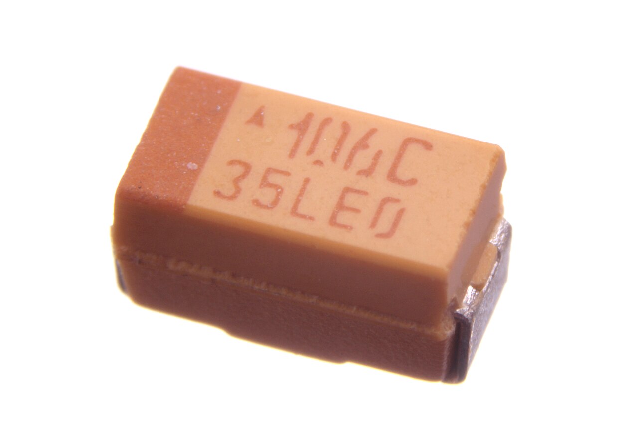
Reverse voltage on a tantalum is not a slow degradation; it is quickly fatal. The Ta₂O₅ dielectric is grown to block current in one direction only, and pushed backward it conducts, leaks, heats, and — in an MnO₂ part — walks straight into the ignition sequence. A tantalum will tolerate only a small percentage of its rated voltage in reverse, briefly, and treating that tiny allowance as design margin is a way to lose hardware. The rule on the bench is blunt: confirm polarity twice before power-on, and never assume the tantalum follows the aluminum stripe convention. The contrast is worth carrying explicitly against the aluminum-electrolytic volume, where the same physical clue means the opposite thing.
9.6 The ignition failure mode, explained plainly
Here is the mechanism the whole reputation rests on, told as a chain of cause and effect. It is worth understanding in full, because every rule of tantalum practice is aimed at breaking one link of it.
It begins with field crystallization. The Ta₂O₅ dielectric is grown as an amorphous film — a glassy, disordered solid with good insulating properties. But amorphous oxide is metastable. Under the electric field of normal operation, and helped along by any impurity, mechanical stress, or thermal cycling, a microscopic region of that film can slowly reorganize into a crystalline form. Crystalline Ta₂O₅ is a far poorer insulator than the amorphous film it replaces; where a crystal grows, a leakage path opens. “Field crystallization” is simply this: the field-driven, gradual conversion of a good glassy insulator into a bad crystalline one at a weak spot. It is the seed of the failure and the reason tantalum reliability is a game of statistics over a population of tiny latent defects.
That leaky crystalline spot passes more current than the sound oxide around it. On its own, at low current, the MnO₂ self-heals it and life goes on. The danger arrives when the circuit can deliver a large current into that spot — which is exactly the case on a low-impedance rail fed by a stiff source. When a tantalum sits directly across a well-regulated supply, or on the input of a DC/DC converter, or hot-plugged onto a charged bus, there is little series resistance between it and a near-infinite reservoir of charge. At the instant of power-on, or at the moment a crystalline path opens, current rushes in — the inrush or surge — limited by almost nothing.
That surge dissipates power in the tiny leaky spot, and the spot heats locally, faster than the surrounding material can carry the heat away. Higher temperature makes the oxide leak still more, which dissipates still more power, which raises the temperature further: thermal runaway, a positive-feedback loop with no natural ceiling. And now the MnO₂ delivers its fatal gift. Heated past its decomposition point, manganese dioxide breaks down and releases oxygen. Sitting right beside it, glowing hot, is metallic tantalum — a metal that burns enthusiastically in oxygen. The result is combustion: the tantalum ignites, and the capacitor flames or bursts, presenting a dead short across the very rail it was meant to stabilize. In effect, an MnO₂ tantalum carries its own oxidizer, so a fault that would merely open another capacitor instead lights a fire.
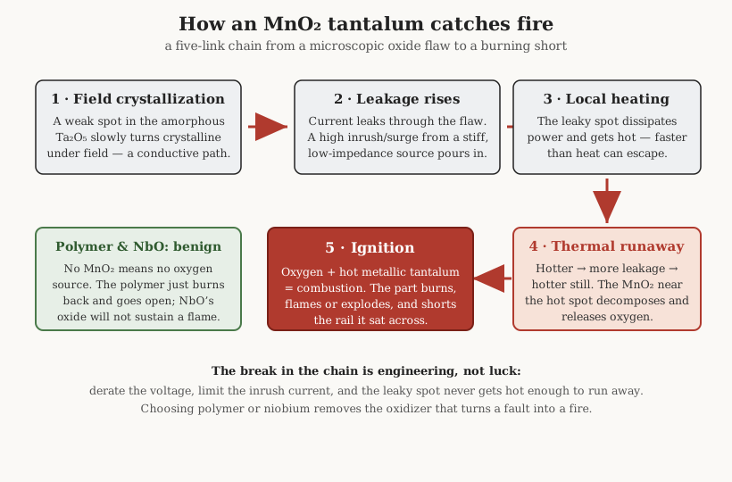
This is why the failures cluster at power-on, not in steady state — the surge is largest when a discharged capacitor first meets the rail. It is why low-impedance, high-inrush positions are the dangerous ones. And it is why the polymer and wet types, lacking a bound-oxygen cathode, cannot sustain the final combustion step even when the earlier links occur.
It is also why manufacturers screen so hard. Because field crystallization is a defect-driven, statistical process, a fraction of any production population carries latent weak spots, and the maker’s job is to weed them out before shipment. Parts are subjected to a factory surge-current test — repeatedly charged through a low impedance at rated voltage, deliberately provoking marginal parts to fail on the line rather than in the field — and to voltage-and-temperature burn-in, so that the survivors’ failure rate follows the low, flat part of the reliability curve. The published failure rates (often quoted as a percentage per thousand hours at a stated voltage and temperature) are the residue of that screening, and they get dramatically better as the applied voltage is derated. This is the deeper reason derating “works”: it is not merely mechanical margin but a move down the statistical curve, away from the operating conditions where the surviving latent defects would eventually be provoked. The engineer’s derating and the manufacturer’s screening are two ends of the same reliability argument.
9.7 Derating as doctrine
Because the failure is real and statistical, tantalum practice has hardened into a set of rules that a working engineer follows without negotiation. They all aim at the same target: keep any latent leaky spot from ever getting hot enough to run away.
The first and most famous is voltage derating. The rule of thumb is to operate a solid tantalum at no more than 50 % of its rated voltage — a 16 V part used on a rail no higher than 8 V. This is not timidity; the surge that a fault draws, and the energy available to heat the spot, both scale with the operating voltage, so halving the voltage buys a large reduction in ignition probability. And for the dangerous positions the derating is stricter still: manufacturers commonly advise derating MnO₂ parts by 50 % in high-surge, low-impedance circuits — directly on a battery, or at a DC/DC converter input — while a benign high-impedance position might get by with only a 20 % derate. The stiffer the source and the larger the possible inrush, the harder the derate. Figure 8 sketches the relationship: the safe fraction of rated voltage falls as the circuit impedance falls.
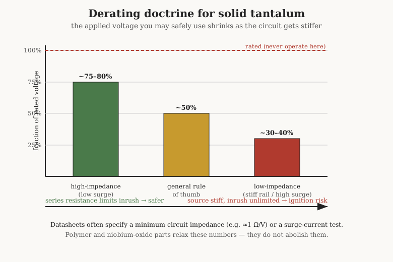
The second rule is inrush and surge-current limiting. Since the ignition chain needs a large current delivered into the fault, denying that current defuses it. A small series resistance — even a fraction of an ohm to a few ohms — between the source and the tantalum limits the inrush at power-on and starves any incipient runaway; datasheets sometimes specify a minimum circuit impedance, on the order of an ohm per volt, precisely for this reason, and qualify parts with a defined surge-current test. A soft-start that ramps the rail rather than snapping it on does the same job. The bench maxim follows directly: never hot-swap a stiff rail with an MnO₂ tantalum without inrush control, because hot-plugging a discharged tantalum onto a charged low-impedance bus is the textbook way to make one ignite.
The third element is chemistry as mitigation. Polymer tantalum reduces the need but does not abolish it. A polymer part still wants voltage derating and still prefers a limited inrush — the field-crystallization and thermal-runaway links of the chain still exist — but because there is no oxidizer, the worst outcome is a benign open rather than a fire, and the practical derating can be relaxed relative to an MnO₂ part. This is the crux of why new designs default to polymer: the same doctrine, with far less at stake if the doctrine is imperfectly followed.
9.8 Niobium: the fire-resistant cousin
The other answer to the ignition problem changes the metal. Niobium-oxide capacitors — commercialized notably under the OxiCap name and pushed by Kemet as a tantalum alternative — build the anode not from tantalum metal but from niobium monoxide (NbO), a conductive ceramic, anodized to a niobium-pentoxide (Nb₂O₅) dielectric. The key property is that NbO is already an oxide: it has a much lower tendency to ignite than metallic tantalum, because it lacks tantalum’s eagerness to grab oxygen and burn. In a breakdown event the temperature rise is markedly lower and the part behaves as a flame-retarding component rather than a fuel source. NbO is, in effect, tantalum’s inherently safer cousin.
Niobium brings two more advantages beyond safety. The raw-material supply is more diversified and cheaper than tantalum’s, which matters both economically and ethically — of which more below. And niobium monoxide offers comparable volumetric capacitance while being roughly half the density of tantalum, so a given part uses less mass of metal. The trade is a somewhat lower performance envelope: NbO parts generally sit at lower maximum voltages and can carry higher leakage than the best tantalum, so they substitute well in low-voltage positions — the sub-10 V rails that dominate modern digital boards — rather than displacing tantalum everywhere. Where the job is bulk decoupling on a low-voltage rail and fire-safety is prized, niobium oxide is a rational, cheaper-metal choice.
9.9 Where tantalum wins, and where it has lost ground
Set against the rest of the passives cabinet, tantalum’s niche is specific and, lately, shrinking. It wins where a designer needs high, stable capacitance in a small, low-profile package and the alternatives fall short: where a Class II MLCC’s DC-bias capacitance loss is unacceptable and its microphonics or cracking are a worry, and where an aluminum electrolytic is too tall, too leaky, or too short-lived. Polymer tantalum’s low ESR makes it strong for point-of-load bulk decoupling and moderate ripple filtering. And in the hermetic wet form, tantalum simply owns the high-reliability corner — military, aerospace, down-hole, and implantable medical — where nothing else combines its energy density, stability, and sealed longevity. The selection volume places these choices in the broader matrix; the short version is that tantalum is the answer when stable capacitance in a small space outranks cost and fire-safety.
It loses, increasingly, on four fronts. Cost: tantalum is an expensive metal and the finished parts are dear. The fire risk: even well-managed, an MnO₂ tantalum is a liability a designer must actively mitigate, and many teams would rather not. The voltage ceiling: the thin oxide caps working voltages far below what film or even aluminum reach. And supply-chain ethics: tantalum is refined from coltan ore, a significant fraction of which comes from conflict-affected regions of central Africa, making it one of the classic “conflict minerals” that responsible-sourcing regulations now track — a real consideration for a modern bill of materials, and part of niobium’s appeal. Meanwhile the competition has closed in from both sides: high-CV multilayer ceramics have grown into capacitance ranges that were once tantalum’s alone, and polymer aluminum capacitors deliver low ESR and high capacitance without tantalum’s cost or fire risk. Between them they have eroded much of the niche tantalum once held uncontested.
9.10 The practical rules, on one card
For the engineer reaching for a tantalum, the doctrine compresses to a handful of non-negotiables. Derate hard — 50 % of rated voltage as the default, tighter on stiff, high-surge rails. Limit the inrush — put a little series resistance or a soft-start between a low-impedance source and the part, and honour any minimum-circuit-impedance the datasheet states. Respect polarity absolutely — the stripe marks plus, the opposite of aluminum, and reverse voltage is quickly fatal. Prefer polymer for new designs — same virtues, benign failure — and reach for niobium oxide where a low-voltage rail wants fire-safety and a cheaper metal. And the bench rule that catches the most hardware: never hot-swap a stiff rail with an MnO₂ tantalum without inrush control. Follow those, and the tantalum earns the trust its density and stability deserve. Ignore them, and it earns its reputation.
Tantalum and niobium sit inside the larger story this deep dive tells: they are the solid-and-dense wing of the electrolytic family, a deliberate counterpoint to the wet aluminum can, and a stark contrast to the DC-bias-limited Class II ceramic. Their construction is a specific application of the sintering and oxide-forming arts covered in the manufacturing volume; their selection is one axis of the trade-off framework in the selection volume. What is unique to them, and worth carrying away, is that they are the family where the failure mode itself drives the design rules — where knowing how a part burns is the same thing as knowing how to use it safely.
Comments (0)