Capacitors · Volume 3
A Short History of the Capacitor
3.1 The urge to store lightning
Every technology has an origin story, and the capacitor’s is unusually good: it begins with a jar of water, a nail, and a series of grown men being knocked flat on their backs. What makes the tale worth telling carefully is that almost everyone involved misunderstood what they had built, and the corrections — where the charge really lives, what the glass is doing, what to call the thing — turn out to be the whole of the physics. The device that stores roughly a nanofarad in a chip smaller than a grain of pepper is the same device, conceptually, as that water-filled jar. What changed in between is two and a half centuries of engineering.
To understand why the first capacitor was such a shock — literally — it helps to remember the state of play in the early 1740s. Electricity was a parlour marvel. Showmen charged people up on insulated stools until sparks flew from their noses; the “electric boy” was suspended on silk cords and made to attract bits of gold leaf. All of this used static electricity generated by friction machines: a spinning glass globe or cylinder rubbed by the hand or a leather pad. The trouble was that the charge would not stay put. Draw a spark and the machine was spent; the electricity leaked away into the air and into everything it touched. Natural philosophers wanted a way to bottle it — to accumulate a large charge and hold it until they were ready to use it. That the answer would arrive in the shape of an actual bottle was a coincidence nobody appreciated at the time.
3.2 The Leyden jar: two men, one very bad afternoon
The first person to succeed was almost certainly not the man the device is named after. Ewald Georg von Kleist, a German cleric and administrator in Pomerania (and, confusingly, no relation to the later poet), found in October 1745 that if he ran a wire from a friction machine into a small medicine bottle partly filled with water or alcohol, and held the bottle in his hand while it charged, he could then draw a startlingly powerful spark by touching the wire. On 11 October 1745 he described the effect in letters to several German experimenters. He was knocked about by his own apparatus more than once.
The catch — and it is a lovely, instructive catch — is that Kleist left out the one detail that mattered: you have to hold the bottle in your hand while charging it. His correspondents in Berlin and Leipzig dutifully wired up their own bottles, set them on the bench as any sensible person would, and got nothing. The instructions were, from their point of view, wrong. The discovery stalled. In hindsight the reason is obvious and it is pure capacitor physics: a hand around the glass is the second plate. Standing on the bench, the outer surface had no return path to earth, so no equal-and-opposite charge could accumulate on the far side of the dielectric, and without that there was nothing to store. Kleist’s own body, gripping the jar, had been quietly completing the circuit the whole time. He had built a two-plate capacitor and mistaken half of it for himself.
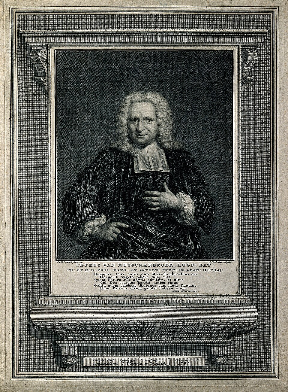
It resurfaced, independently, at the University of Leiden in the Netherlands (Leyden, in the old spelling). There Pieter van Musschenbroek, a distinguished professor of physics, was experimenting along similar lines. In January 1746 a visitor to his laboratory, a lawyer named Andreas Cunaeus, tried to reproduce an experiment on his own and — being an amateur — happened to hold the charging jar in his hand, exactly the thing the professionals knew better than to do. The discharge nearly finished him. Musschenbroek then tried it himself and received a blow he described in famously terrified terms, writing to a colleague in Paris that he would not take a second such shock for the whole kingdom of France, and advising him never to attempt it. The device was christened the Leyden jar after the university, and Musschenbroek — the man who nearly died of it rather than the man who invented it — got the naming rights of history.
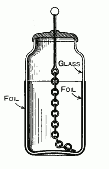
What was the jar, really? Strip away the water and it is the most basic capacitor imaginable: two conductors separated by an insulator. The inner conductor was the water (later, a coating of metal foil on the inside of the glass); the outer conductor was the experimenter’s sweaty hand wrapped around the bottle (later, foil glued to the outside); the insulator — the dielectric — was the glass wall between them. Hold the jar, feed charge to the inner conductor, and an equal and opposite charge is drawn onto the outer one through your body and the ground. The glass keeps the two from meeting. Break the circuit and the charges sit there, straining across the glass, until you offer them a path — at which point they reunite in a single violent spark. That is a capacitor charging and discharging. Everything since has been refinement.
The jar was a sensation, and it made possible a demonstration that has never been bettered for sheer theatre. In 1746 the Abbé Jean-Antoine Nollet, France’s leading electrical showman and no friend of the theories that were about to overturn his own, arranged for the King’s guardsmen — by one account a hundred and eighty of them — to join hands in a line, then discharged a Leyden jar through the human chain. The whole line leapt into the air at once. Not content, he later strung a ring of some two hundred Carthusian monks together with lengths of iron wire, the circuit more than a kilometre around, and discharged the jar again. The white-robed monks sprang up in unison. Nollet’s serious aim was to time how fast the electric “virtue” travelled, but the monks all jumped at what looked like the same instant — an early, crude demonstration that electricity moves through a conductor very fast indeed. What he had actually built was the eighteenth century’s largest ESR measurement, though nobody would have put it that way.
3.3 Franklin, and the charge that lives in the glass
The man who made sense of the jar was working in Philadelphia. Benjamin Franklin took up electricity in the late 1740s with the zeal of a hobbyist who happens to be a genius, and within a few years he had reorganised the whole subject.
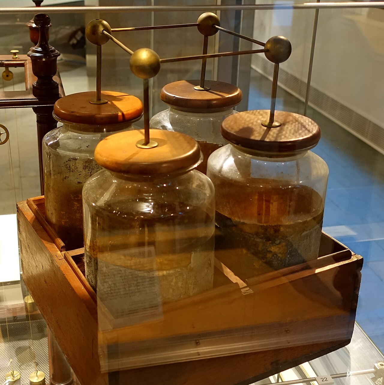
Three of his contributions belong in any capacitor’s family history. The first is a word. Wanting more stored charge than a single jar could hold, Franklin wired several jars together with their inner coatings joined and their outer coatings joined — a parallel connection, in modern terms, which adds the capacitances — and called the assembly an electrical battery, borrowing the military term for a row of cannon massed to concentrate their fire. The word stuck. When we say “battery” today we usually mean a stack of electrochemical cells, an invention still half a century in the future; but the term was coined for a bank of capacitors, and it means, at root, several of the same thing ganged together for greater effect. Figure 1 shows exactly such a battery of Leyden jars.
The second contribution is his one-fluid theory. Where others imagined two distinct electric fluids, Franklin proposed a single fluid present in all matter. An object with a surplus he called positive (plus); one with a deficit, negative (minus). Charging did not create electricity, it merely moved this fluid from one body to another, so that whatever one gained the other lost — the first clear statement of what is now called conservation of charge. His sign convention, chosen before anyone knew electrons existed, is the reason conventional current is defined as flowing from plus to minus while the electrons that actually carry it in a wire trudge the other way. Every EE has cursed that arbitrary choice; it is Franklin’s.

The third — and the most modern — is his answer to a question the Leyden jar posed and nobody had settled: where, exactly, is the stored charge? The obvious guess was that it sat in the water, or the inner foil, as water sits in a cup. Franklin doubted it. He devised what became known as the dissectible (take-apart) Leyden jar, whose foil linings could be lifted off the glass after charging. He charged the jar, carefully removed the inner and outer conductors, handled them, reassembled the whole thing — and drew nearly the full spark from it anyway. The charge had not gone off with the metal. It had stayed in the glass. Franklin concluded, correctly, that the electrical energy resided in the insulator between the plates, not on the plates themselves.
That is a genuinely deep insight, and it is worth pausing on, because it is the thing the whole rest of this deep dive is about. The action of a capacitor happens in the dielectric — the stressed, polarised insulating material sitting in the electric field. The plates are just there to set up the field and to get the charge in and out. Choose a better dielectric and you get a better capacitor; that single sentence explains why the family tree branches into ceramic and film and electrolytic and mica, each argument about which insulator to stress and how. Franklin saw the essential point with a jar and a hunch, a full century before anyone could say why the glass mattered. And of course, in 1752, he flew the kite — drawing charge from a storm cloud down a wet string into a Leyden jar, proving that lightning and the spark from a friction machine were the same phenomenon, only scaled up. The urge to bottle lightning had, in a manner of speaking, succeeded.
3.4 What to call it: condenser, capacitor, and the ghost on the tube chassis
For most of the nineteenth century and well into the twentieth, the device was not called a capacitor at all. It was a condenser. The name traces to Alessandro Volta, who around 1780 built an instrument he called a condensatore — a “condenser” — because it condensed electric charge, packing a greater density of it onto a conductor than that conductor could hold on its own. (Volta, incidentally, is the same man who a few years later invented the electrochemical pile that stole the word “battery,” and who lent his name to the volt. The early history of electricity is a small world.) The Latin root gave the word to nearly every European language, which is why a French or German or Italian datasheet still speaks of a condensateur, Kondensator, or condensatore today.
“Condenser” had a problem: a steam condenser is a completely different object, and as electrical and mechanical engineering both industrialised the collision got annoying. The British Engineering Standards Association recommended capacitor in 1926, from capacity — the thing’s ability to hold charge — and the standards bodies pushed it steadily through the following decades. Engineers, being engineers, took their time. “Condenser” clung on for two full generations in the places where old vocabulary goes to hide: on the schematics of vacuum-tube radios and televisions, on the parts lists of hi-fi amplifiers, and — most durably of all — under the bonnet of every car and small engine with breaker-point ignition, where the little cylinder wired across the points has been called an “ignition condenser” since the Model T and will be until the last points-and-condenser magneto rusts away. Walk into a small-engine shop and ask for an ignition capacitor and you may still get a puzzled look. The marking conventions and the folklore of these old parts get their own treatment in the markings volume and the paper-capacitor volume; here it is enough to know that “condenser” and “capacitor” are the same thing, viewed from different decades.
3.5 Faraday, the dielectric, and the unit that isn’t the man
If Franklin located the action in the dielectric, Michael Faraday explained it. In the 1830s Faraday — a bookbinder’s apprentice turned the greatest experimental physicist of his age — set out to understand what an insulator actually does in an electric field. He built matched capacitors identical but for the material filling the gap, charged them the same way, and measured how much more charge each could hold. Glass, shellac, sulphur, and the rest each held more than empty space did, and each by a characteristic factor. Faraday called this property the material’s specific inductive capacity; today we call it the relative permittivity or dielectric constant, the number that says how many times better than vacuum a given insulator is at storing field energy, and the single most important figure of merit in any capacitor datasheet. (Air is about 1; ordinary glass, a few; the barium-titanate ceramics in a modern chip capacitor, into the thousands. That the physics of the whole component reduces to that one ratio is the through-line from the analysis in the earlier volumes to every technology that follows.)
Faraday’s picture of why it happened — the insulator’s molecules straining and aligning under the field, storing energy in that strain — is essentially the modern one, and it is treated in full in the earlier volume on the real capacitor. His experiments also gave us the idea of the field itself, lines of force filling the space between the plates, which is the mental furniture every EE now uses without thinking.

Now, a point that is muddled almost everywhere, so it is worth getting exactly right: Faraday did not invent, define, or name the farad. The farad, the SI unit of capacitance, was named in his honour — as the ohm honours Ohm and the volt honours Volta — but the naming was the work of a committee, and it happened after his death. The name was first proposed in 1861 by the British electrical engineers Latimer Clark and Sir Charles Bright, in a paper to the British Association for the Advancement of Science on standardising electrical units. In their proposal the “farad” was actually a unit of quantity of charge, not capacitance. It was only when the BAAS Committee on Electrical Standards — a body that at various times included William Thomson (later Lord Kelvin), James Clerk Maxwell, and Werner von Siemens — sorted the units out through the 1860s and reported in 1873 that the farad settled into its modern role as the unit of capacitance. The International Congress of Electricians in Paris made it official in 1881. So the man measured the dielectric; the unit that bears his name was defined by others, later, and even then took twenty years to mean what it means now. One farad, it turned out, is an enormous capacitance — a jar the size of a house — which is why the real world runs on microfarads, nanofarads, and picofarads, a millionth, a billionth, and a trillionth of the honoured unit.
3.6 From curiosity to component: telegraphy, telephony, and the radio boom
Through the middle of the nineteenth century the capacitor remained mostly an instrument of the laboratory and the lecture hall. What turned it into a manufactured component — something ordered by the thousand from a catalogue — was the electrical communications industry.
The submarine telegraph cables of the 1850s and 60s behaved, maddeningly, like enormously long, thin capacitors: the copper core, the seawater outside, and the gutta-percha insulation between them stored charge along every mile, smearing out the crisp telegraph pulses into sluggish blurs. Understanding that capacitance — and Faraday, Thomson, and others did the work — was a commercial necessity, not an academic nicety. Telephony, arriving in the 1870s and 80s, needed capacitors as discrete parts: to block direct current while passing the alternating voice signal, the “coupling” job that is still a capacitor’s daily bread.
But the technology that truly made the capacitor a mass-produced object was radio. A tuned radio circuit is, at heart, a capacitor and an inductor swapping energy back and forth at a resonant frequency; change the capacitance and you change the station. From Marconi’s spark transmitters at the turn of the century — which stored their punch in banks of Leyden jars and, later, glass-plate capacitors, the direct descendants of Musschenbroek’s bottle — through the broadcast boom of the 1920s, radio consumed capacitors in three great roles it still fills: the variable “tuning condenser” with its interleaved air-spaced plates that you rotated to pick a station; the small fixed capacitors that tuned and bypassed individual stages; and the large ones that smoothed the rectified mains into clean direct current for the tubes. Radio is where the capacitor stopped being a piece of physics and became a line item.
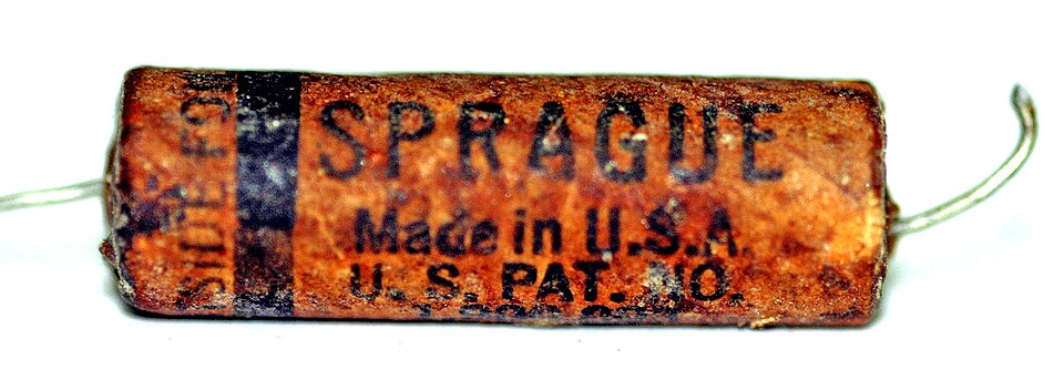
The workhorses of that era were flat sandwiches of metal foil and waxed or oiled paper, rolled up tight to pack a useful capacitance into a small tube, then dipped in wax or sealed in a cardboard or, later, a moulded case. Cheap, made by the mile, and — as anyone who has restored a vintage radio knows — destined to go leaky with age, which is exactly why “recapping” old gear is a thing and why paper capacitors get a whole volume of their own later in this dive. The manufacturing method itself is worth flagging, because it outlived the material: the wound roll — two strips of electrode and two of dielectric, spooled together on a machine and sealed — is still exactly how film and aluminium-electrolytic capacitors are built today, as the manufacturing volume describes. Only the ribbon fed into the winder changed, from waxed paper to plastic film. The geometry Musschenbroek would have recognised as a jar had become a Swiss roll, but it was still two conductors and a dielectric, wound instead of stood upright.
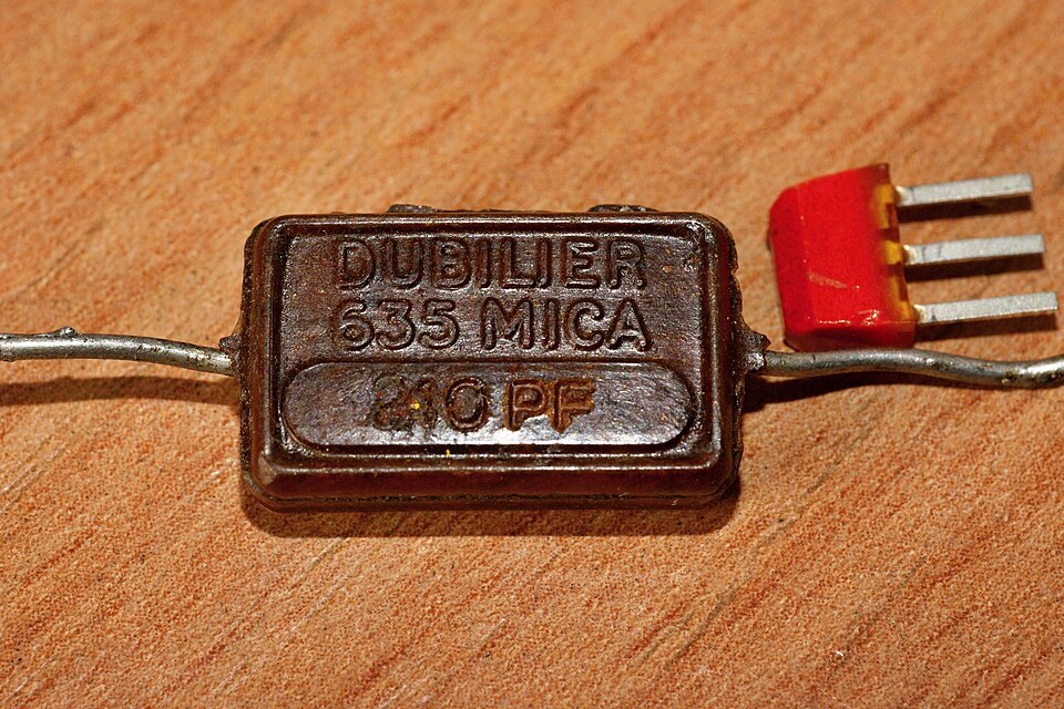
For jobs that demanded stability and precision — the frequency-setting capacitors in a transmitter, the timing elements in test gear — paper was too loose and too drifty. The answer was mica, the naturally occurring mineral that cleaves into flawless, thin, heat-proof sheets with an excellent dielectric constant and beautifully low loss. Early mica capacitors clamped stacks of mica sheets between foils; by the 1920s and 30s they had evolved into the neat moulded-Bakelite “postage-stamp” mica capacitors that populated radio and instrument circuits for decades, their values often read off a code of coloured dots stamped on the case — a scheme decoded in the markings volume. Silver-mica capacitors, with the electrodes fired directly onto the mica as a silver film, carried that tradition into the era of precision RF and are still specified today where a few picofarads must not drift.
3.7 The electrolytic revolution: cheap capacitance, and mains power for everyone
There was one thing foil-and-paper and mica could not do: deliver a large capacitance in a small box at low cost. The values needed to smooth rectified mains into steady DC — tens or hundreds of microfarads — would have taken a paper capacitor the size of a paint can. The breakthrough that solved it is one of the quiet turning points of twentieth-century electronics.
In 1896 a researcher named Charles Pollak (Karol Pollak), working on electrolysis with alternating current, noticed that a thin oxide film formed on an aluminium electrode in a suitable electrolyte and behaved as an insulator — one that stayed put even when the power was removed, provided the polarity was kept the right way round. He patented the idea (German patent DRP 92564, granted 1897): a “liquid condenser” with aluminium electrodes in a borax electrolyte. The magic of the electrolytic capacitor is that its dielectric is that aluminium-oxide film, and it is fantastically thin — a fraction of a micrometre — so the capacitance packed into a given volume is enormous. The price is that the film only insulates in one direction, which is why an electrolytic is polarised and why connecting one backwards ends, sooner or later, in a bang.
The first electrolytics were wet: an aluminium anode standing in a jar of liquid electrolyte. They worked, they were used briefly in 1920s radios, but they were messy, they could freeze or dry out, and they did not travel well. The transformative step was the dry — really, damp — electrolytic of the mid-1920s and 30s, in which the liquid was replaced by an electrolyte-soaked paper spacer, and the whole aluminium-paper-aluminium sandwich was rolled up like the paper capacitors before it and sealed in a compact can. Suddenly a big smoothing capacitor was small, rugged, sealed, and cheap. That is not a footnote. The dry electrolytic is a large part of why the mains-powered radio replaced the battery set — it made the reservoir capacitor in an AC power supply affordable and small enough to put in every living-room cabinet in the industrial world. The full story of the etched-oxide anode, the electrolyte chemistry, ripple current, endurance, and the notorious “capacitor plague” belongs to the electrolytics volume; here it is the plot point that made electronics a mass-market business.
3.8 Ceramic, the multilayer chip, and the age of trillions
The next great dielectric was ceramic. Certain ceramics — especially those based on barium titanate, exploited from the 1940s onward — have dielectric constants in the hundreds or thousands, wildly higher than glass or mica, which means a lot of capacitance from a very little material. The classic result was the ceramic disc capacitor, the little orange or blue lollipop soldered into essentially every tube and transistor radio, television, and piece of consumer gear for decades: cheap, small, and good enough for bypass and coupling duty where precision did not matter.
The revolution, though, was learning to stack the ceramic. Instead of one disc, print electrodes onto many wafer-thin ceramic layers, interleave them, and fire the whole thing into a solid monolithic block — a multilayer ceramic capacitor, the MLCC. Every layer adds capacitance in parallel (Franklin’s battery trick, shrunk to microscopic scale), so a block the size of a sesame seed can hold what once took a can. The technique matured from the 1960s — the miniaturisation demands of the Apollo programme and military electronics were an early driver — and the arrival of surface-mount assembly in the 1980s, which did away with wire leads entirely in favour of a bare block soldered flat to the board, let the MLCC take over the world.
And take over it did. The modern MLCC is the most-manufactured man-made object of all time by a wide margin: the world turns out something on the order of several trillion of them every year — recent estimates run past four and a half trillion. A single smartphone contains roughly a thousand of them, tucked around every chip to steady its power. The families that make them read like a directory of Japanese and American industry — Murata, TDK, Taiyo Yuden, Samsung Electro-Mechanics, Kemet, Vishay, Nichicon, Panasonic — and when a shortage hits, as it periodically does, it can idle car and phone factories worldwide, because the humble ceramic chip is the rice of electronics. The alphabet soup on their datasheets — C0G, X7R, X5R and the rest — encodes exactly which barium-titanate recipe is inside and how it behaves with temperature and voltage, and it gets decoded in the ceramics volume.
Two more branches complete the modern picture. Tantalum capacitors, invented at Bell Labs in the early 1950s to complement the brand-new transistor and refined into a manufacturable product by Sprague later that decade, used a sintered tantalum-powder slug with a manganese-dioxide solid electrolyte to pack electrolytic-scale capacitance into a small, stable, solid part — ideal for the miniaturised military and industrial electronics of the post-war years, and a story told in full in the tantalum volume. And film capacitors — thin ribbons of plastic such as polyester (Mylar/PET) and polypropylene, metallised or interleaved with foil — steadily displaced the old wax-paper types from the 1950s on. Plastic film does not absorb moisture, does not go leaky with age the way paper does, and can even “self-heal” a puncture; it is simply a better insulator to stress, so paper had to go. Why, and where each film wins, is the subject of the film-capacitor and paper-capacitor volumes.
3.9 The jar and the chip
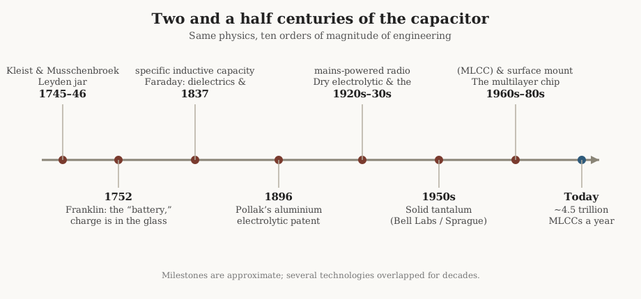
It is worth ending where a good history should, by measuring the distance travelled. Musschenbroek’s jar of 1746 stored, very roughly, a nanofarad — a billionth of a farad — in an object you held in two hands, at the constant risk of being flung across the room. A modern 0201-case MLCC stores a similar nanofarad, or a hundred times more, in a block a fifth of a millimetre long that a machine places at a rate of tens of thousands an hour, and that you could lose in the carpet. Between those two objects lie ten orders of magnitude of engineering: thinner dielectrics, better insulators, cleverer geometry, and a manufacturing scale that runs to trillions.
Yet the physics has not moved an inch. Both are two conductors with an insulator between them, storing energy in the strained electric field of that insulator — the field that Franklin located in the glass with a take-apart jar and a good guess, that Faraday explained by measuring how much more charge different insulators would hold, and that every one of the volumes in this dive is, in the end, about. The Leyden jar was not a primitive ancestor that we have outgrown. It was the whole idea, complete on the first afternoon, waiting two hundred and fifty years for the engineering to catch up.
Comments (0)