Capacitors · Volume 12
Choosing the Right Capacitor: A Selection Guide by Job
12.1 There is no best capacitor
Every volume before this one has argued the same quiet point from a different angle: a capacitor is a bundle of compromises, and each family strikes the bargain differently. The ceramic volume showed a part that packs enormous capacitance into a grain of rice and then hands back only a third of it under bias. The film volume showed a part that never lies about its value and never sets fire to anything, but costs board space and money by the fistful. The electrolytics volume showed the champion of cheap bulk farads, wearing an expiry clock on the side of the can. The tantalum volume showed the densest, steadiest small capacitor there is — which occasionally ignites. Put those portraits side by side and the conclusion writes itself: there is no best capacitor, only the best fit for a particular job.
This is the volume that does the fitting. It assumes the reader has met the families and knows, at least in outline, what an X7R does under DC bias and why a wet electrolytic dies of thirst. What it adds is the selection framework — the disciplined way an engineer moves from “I need a capacitor here” to a specific part number — and then the heart of the matter, a walk through the common jobs a capacitor is asked to do, with a default answer and a warning for each. A hobbyist should come away knowing what to drop into a given socket. An experienced engineer should come away with a checklist rigorous enough to defend at a design review.
The mindset worth adopting before any part is chosen is that a capacitor is specified by what it must do in the circuit, not by the number printed on it. “A 10 µF capacitor” is not a specification; it is the beginning of one. Ten microfarads of what — held to what tolerance, over what temperature, at what voltage and how much of its rating, carrying how much ripple, at what frequency, in a signal path or on a power rail, for how many years, at what price, and does it hang across the mains? Answer those and the family usually chooses itself. Skip them and the bench will answer them for you, later and more expensively.
12.2 The parameters that decide it
Selection is really the ordered application of a dozen questions. Not all matter in every job — a decoupling cap does not care about dielectric absorption, a timing cap does not care about ripple current — but running the full list quickly is how an engineer avoids the classic mistake of optimising the one parameter they happened to think of and being ambushed by another. The questions, roughly in the order they tend to matter:
Required value and tolerance. How many farads, and how tightly? A reservoir capacitor’s value is nearly irrelevant — anything within a factor of two will do, which is why an electrolytic’s ±20 % is no obstacle. A timing or filter capacitor’s value is the specification, and a ±20 % part would put the frequency 20 % wrong. This single split — is the value a target or a suggestion? — separates the precision families (Class I ceramic, film, silver mica) from the bulk families (electrolytic, Class II ceramic, tantalum) before any other question is asked.
Working voltage and derating margin. The rail voltage sets a floor under the rating, but the rating you actually buy sits well above it, because every family wants headroom — and, as the non-idealities volume laid out, for different reasons. A Class II ceramic wants margin to keep its capacitance from collapsing under bias; a tantalum wants it to stay off the ignition curve; an electrolytic wants it for endurance. Derating is not timidity, and it gets its own section below.
Ripple current and self-heating. If AC current flows through the part — and in any power-supply role it does — that current dissipates I²·ESR watts inside a small object, and the resulting core temperature, not the value, is what governs the part’s life. For reservoir and output capacitors the ripple-current rating is the headline number, above capacitance and above voltage.
ESR and impedance at the frequency of interest. A decoupling capacitor is only as good as its impedance at the noise frequency, and that impedance bottoms out at the ESR, no matter how many farads are stacked behind it. The real-capacitor volume’s impedance-versus-frequency curve — falling, bottoming at the self-resonant frequency, then rising as the part turns inductive — is the picture to hold in mind here.
Stability over voltage, temperature, time. Will the value the circuit sees at 25 °C and no bias survive a cold morning, a hot enclosure, a decade of aging, and the operating voltage? Class I ceramic and film hold; Class II ceramic and electrolytic wander; the wandering is fine for bulk and fatal for precision.
Polarity. Can the part be non-polar, or is a fixed DC polarity guaranteed? An AC-coupled signal or a mains filter must be non-polar (ceramic, film, or bipolar electrolytic); a DC rail can use a polarised electrolytic or tantalum — provided it goes in the right way round, and provided the reader remembers that the aluminium stripe marks minus while the tantalum bar marks plus.
Size, height, and mounting. The flat tantalum that hides under a connector, the tall electrolytic that will not fit under a card, the 0402 ceramic that survives board flex better than a 1210 — mechanical fit is a real constraint, not an afterthought, and it interacts with the electrical choice (a smaller ceramic case droops harder under bias but resonates higher and cracks less).
Temperature range and lifetime. Will it see automotive under-hood heat or Arctic cold? The dielectric’s rated range is a survival limit, distinct from its temperature coefficient; and for electrolytics, temperature is the master dial on the wear-out clock.
Cost, and safety or agency approval. Pennies matter at volume, and some positions — anything across the mains — are governed not by preference but by law: only an agency-approved X- or Y-class safety part belongs there.
12.3 The master comparison table
Before the job-by-job walk, it helps to see the families laid against one another on the properties that decide selection. The matrix below is the volume’s signature: ten families down the side, the deciding properties across the top, colour-coded so that no family reads as green across the board — which is the whole lesson.
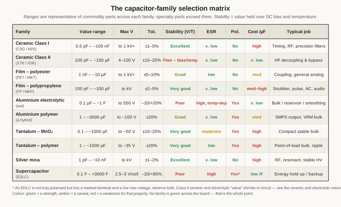
Reading down the columns tells the story the family volumes told one at a time. Value range: the electrolytic and supercapacitor own the high end (millifarads to farads), Class II ceramic and the tantalums fill the microfarad middle, and Class I ceramic, silver mica, and film hold the picofarad-to-nanofarad precision corner. Stability: the paraelectric and film dielectrics (Class I ceramic, polypropylene, polystyrene, silver mica) are excellent, the ferroelectric Class II and the electrolytics poor — the direct consequence, as the ceramics volume argued, of trading permittivity for a value you can trust. ESR: ceramic, polymer, and film sit at the low-impedance end that suits high-frequency and ripple work, while the wet electrolytic sits at the high, temperature-swinging end that suits only low-frequency bulk. Cost per farad: the wet electrolytic and Class II ceramic are almost free, film and tantalum dear, and the ranking flips entirely if you price per farad you can actually trust rather than per nameplate farad.
Two entries in the “value” column deserve the asterisk they carry, and both were laboured in their own volumes: a Class II ceramic’s marked value is a zero-bias, room-temperature, freshly-fired figure that shrinks once the part is soldered onto a live rail, and an electrolytic’s value is loosely toleranced to begin with and drifts as it ages. The matrix lists the nameplate ranges; the in-circuit reality is smaller, and the ceramics and electrolytics volumes give the discount. The supercapacitor’s asterisk flags that it is not strictly polarised but does carry a marked terminal and a very low per-cell voltage, both of which must be respected.
The matrix is a map, not a verdict. It narrows ten families to two or three candidates for a given job; the job-specific reasoning below picks the winner.
12.4 Selection by job
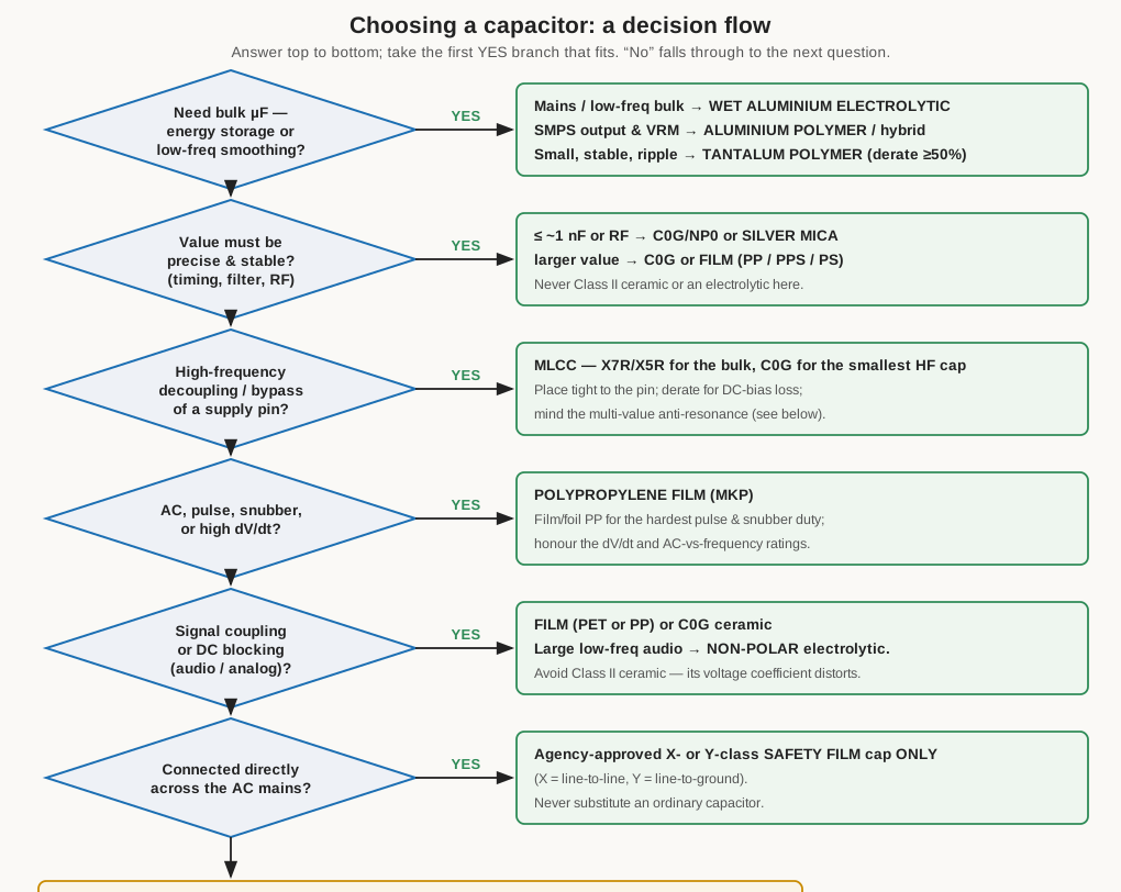
Here is the heart of the volume. Each common capacitor job has a default answer, a part to avoid, and a reason rooted in the physics the earlier volumes established. The decision flow in Figure 3 compresses the whole section into a single top-to-bottom path; the prose that follows fills in the why.
12.4.1 Decoupling and bypass — the local high-frequency job
The most common capacitor job on any digital board is decoupling: giving a chip’s power pin a local reservoir of charge so that when the chip suddenly draws current — on every clock edge, as its logic switches — that current comes from a capacitor a millimetre away rather than through the inductance of the trace back to the regulator. The bypass capacitor’s task is to present a low impedance between the rail and ground across the frequencies the chip’s switching contains, which reach well into the hundreds of megahertz. That is a high-frequency job, and it is won by low ESL and a high self-resonant frequency, not by raw capacitance.
The default answer is the multilayer ceramic chip capacitor (MLCC), and the reason is exactly the one the ceramics volume gave: its stacked, short-path construction has the lowest ESL and ESR of any capacitor family, so its impedance curve bottoms out low and its self-resonant frequency sits high. For the bulk of the decoupling — the hundred-nanofarad-to-few-microfarad workhorse cap sitting on each power pin — an X7R or X5R (Class II) part is the sensible choice: it delivers real capacitance in a tiny case, and the fact that its value sags under bias and drifts with temperature simply does not matter when the job is “be a low impedance,” not “be exactly 100 nF.” For the fastest transients and the highest self-resonant frequency, a small C0G/NP0 cap earns its place: its value is smaller, but its loss is lower and its behaviour cleaner at the top of the band.
Three refinements separate a decoupling scheme that works from one that merely looks right on the schematic. The first is placement and package: the impedance minimum is set as much by the mounting inductance — the loop from pad through via to plane and back — as by the part, so the smallest case that carries the value, placed as close to the pin as the layout allows on short, fat vias, is the better high-frequency bypass. An 0402 resonates higher than an 0805 of the same value, and a cap on the far side of the board through a long via is half wasted.
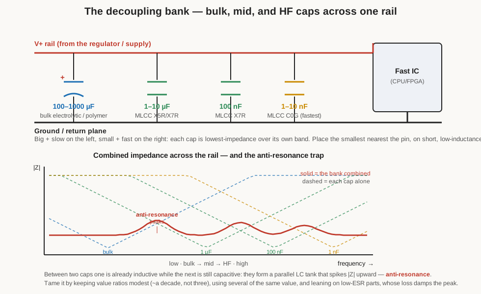
The second is the multi-value bank and its trap. The instinct to cover a wide band by paralleling a bulk cap, a mid cap, and a small cap is sound, and Figure 4 shows the arrangement — but it carries the anti-resonance hazard the non-idealities volume warned of. Where a larger cap has gone inductive (above its self-resonant frequency) and a smaller one is still capacitive, the two form a parallel LC tank, and at its resonance the combined impedance spikes upward. Stack too many disparate values and the rail’s impedance grows a picket fence of peaks precisely where it was supposed to be smooth. The cures are the ones that volume gave: keep the value ratios modest — roughly a decade apart, not three — prefer several capacitors of the same value over a menagerie of different ones, and lean on low-ESR parts, because ESR is what damps the anti-resonant peak.
The third refinement is DC-bias derating for ceramics, and it is the one that bites hardest. A “10 µF” X5R in a small case on a 3.3 V rail may be delivering three or four microfarads once biased, as the ceramics volume detailed. If the design needs ten microfarads of actual bypass, it must either over-specify the ceramic (buy a 22 µF part to net 10 µF in circuit), move up a case size or a voltage rating to flatten the bias curve, or reach for a tantalum or polymer part whose capacitance is flat versus voltage. Trusting the marked value on a high-K ceramic bypass is the single most common way a rail ends up with a fraction of the bulk its designer thought they had placed.
12.4.2 Bulk, reservoir, and smoothing — the low-frequency energy job
Where decoupling is about high-frequency impedance, bulk storage is about holding a rail up through the low-frequency troughs: smoothing the 100 or 120 Hz ripple after a mains rectifier, or supplying the slow, heavy current swings a converter and its load demand between switching cycles. This wants farads, and cheaply, and the frequencies are low — which is precisely the electrolytic’s territory.
For mains-derived bulk and reservoir duty the default is the wet aluminium electrolytic: nothing else buys thousands of microfarads at hundreds of volts for pennies. The selection within the family is governed, as the electrolytics volume insisted, by ripple current and ESR, not capacitance: specify a low-ESR series, a 105 °C rating for thermal headroom and life, and a ripple-current rating that meets or beats the application at its actual ripple frequency (using the datasheet’s frequency multipliers), and mount the part away from hot components so the Arrhenius clock runs slow. Under-rating the ripple is how a “correct” reservoir cap cooks itself; the section on common mistakes returns to it.
For the output of a switch-mode supply, and for the point-of-load bulk near a modern CPU’s voltage regulator, the frequencies are higher (tens to hundreds of kilohertz) and the premium is on low ESR, so the modern default has shifted to the aluminium polymer (or hybrid) capacitor and, where the profile must be flat and the value stable, the polymer tantalum. Both deliver near-ceramic ESR at electrolytic-scale capacitance, which is why a quality motherboard advertises “all solid capacitors.” In every one of these bulk roles the electrolytic or polymer part is paired with ceramics: the big slow tank handles the low-frequency energy, and a clutch of small MLCCs at the load handles the high-frequency bypass that the bulk part’s ESR and ESL cannot. They are a team, not competitors, as both the electrolytics and non-idealities volumes stressed.
12.4.3 Coupling and DC-blocking — the signal-path job
A coupling capacitor passes an AC signal from one stage to the next while blocking the DC bias difference between them. The value is chosen so the capacitor’s reactance is small at the lowest signal frequency of interest — a high-pass corner — and the tolerance is usually loose. What is not loose is the demand for linearity: whatever imperfection the dielectric carries lands directly in the signal, so a coupling cap in a quality analog or audio path must not add distortion.
This disqualifies Class II ceramic from any signal path where quality matters, and the reason is specific and measurable: a ferroelectric dielectric’s capacitance depends on the instantaneous voltage across it (a voltage coefficient), so as the signal swings, the capacitance moves with it, and a capacitance that moves with the signal is, by definition, distortion. The ceramics volume flagged the effect; here is where it bites. The default for a small-signal coupling cap is therefore film (polyester or polypropylene) or, for the smaller values, C0G/NP0 ceramic — all of them flat, low-loss, and non-polar. Polyester is the everyday workhorse; polypropylene is the choice where the last word in transparency is wanted, for the low-loss, low-absorption reasons the film volume gave (and, yes, the reason audiophiles pay for it).
For a large low-frequency coupling capacitor — the tens of microfarads a loudspeaker crossover or an audio inter-stage sometimes needs, where a film part would be the size of a fist — the answer is the non-polar (bipolar) electrolytic, built with two anode foils back to back so it tolerates either polarity. It is looser and lossier than film, but it is the only affordable way to get large non-polar capacitance, and it is exactly what the electrolytics volume described in crossover duty. What one must never do is use a polarised electrolytic on a signal that swings both ways, or a high-K ceramic where the coupling quality matters.
12.4.4 Timing, oscillators, and integrators — the value-must-be-right job
When a capacitor sets a frequency or an integration rate — the RC in a timer, the tank in an oscillator, the feedback cap in an integrator or analog computer — its value is the specification, and two further demons appear that decoupling never has to face: the temperature coefficient (drift moves the frequency) and dielectric absorption (the “soakage” the non-idealities volume described, where charge thought gone creeps back and corrupts a held or integrated value).
The default is C0G/NP0 ceramic: near-zero tempco (0 ± 30 ppm/°C), negligible voltage and aging drift, and dielectric absorption below a tenth of a percent — the value stays put and the charge stays put. For larger values or the most demanding low-absorption work, polypropylene and (in vintage or specialist gear) polystyrene film are the film answers, both with dielectric absorption in the hundredths of a percent; polystyrene’s small negative tempco (about −125 ppm/°C) was famously paired with an inductor’s positive drift to build temperature-stable LC circuits. At radio frequencies silver mica joins the list for its stability and high Q. What is categorically disqualified is Class II ceramic (its value sags, drifts, and ages — the frequency would wander with temperature, bias, and time) and any electrolytic (loose, lossy, and leaky — the charge would not even stay on the plates). The measurement and non-idealities volumes gave the numbers; the selection rule is simply: timing wants a paraelectric or a good film, never a ferroelectric or an electrolyte.
12.4.5 Filtering — analog, PLL loop, and RF
Filtering is a close cousin of timing: an analog filter’s corner frequency, a phase-locked-loop loop filter’s dynamics, an RF network’s tuning all depend on a capacitance that is predictable and stable. The requirements track timing almost exactly — C0G ceramic for the smaller values, film (PP or PPS) for the larger, silver mica for RF — and for the same reasons: a stable, low-loss, low-absorption value that does not move with temperature or bias. Two filtering-specific notes are worth adding. In a PLL loop filter the capacitor’s dielectric absorption directly affects settling and jitter, which is why C0G or film is specified there and Class II ceramic avoided despite the tempting capacitance density. And where two capacitors must track over temperature — a matched pair in a differential filter, say — matching their temperature coefficients matters as much as their absolute value, which is a job for the tightly-specified Class I tempco ladder (the P- and N-series the ceramics volume tabulated) rather than a broadly-toleranced Class II part.
12.4.6 Snubbers, dV/dt, and pulse — the punishing-current job
A snubber capacitor sits across a switching device or a transformer winding to absorb the energy in a fast voltage transient and tame the ringing when a switch opens. It is asked to swallow steep edges — high dV/dt — and the current that a steep edge drives through a capacitor is I = C·dV/dt, which can be large and brief. The limiting rating here is often not voltage at all but dV/dt and peak current, and the part must survive them repeatedly without its electrode connection overheating.
The default is polypropylene film, and specifically the film/foil (rather than metallized) construction for the hardest duty, because — as the film volume explained — the solid foil electrode carries heavy pulse current where a thin metallized layer would overheat at the end connection. Polypropylene’s low loss means it runs cool under AC, and its self-healing (in metallized grades) gives graceful failure. Specialised snubber-capacitor series exist for exactly this role, rated in dV/dt and peak current and often built film/foil. What must be avoided is polyester (too lossy — it cooks under heavy AC), Class II ceramic (which not only distorts but, being piezoelectric, sings under a switching waveform), and any electrolytic (far too slow and lossy). The one place a ceramic does snub is a small RC snubber at modest energy, and even there a C0G or a purpose-made pulse ceramic is preferred over a high-K part.
12.4.7 Resonant, RF power, and high voltage — the low-loss, high-stress job
In a resonant converter tank, an RF power amplifier’s matching network, or a tuned high-voltage circuit, the capacitor carries large circulating currents at frequency and stands off high voltage, and any loss shows up as heat and any drift detunes the circuit. This is a demanding intersection of low loss, high current, high voltage, and stability. The answers, depending on scale: silver mica and C0G ceramic for the low-power, stable, high-Q positions (RF tuning, tight resonators); polypropylene film for the higher-current, higher-energy resonant and AC roles, where its low loss lets it be pushed hard; and dedicated ceramic or vacuum high-voltage capacitors for RF power and transmitter duty, where the voltage and current exceed what a chip part can bear. The through-line is loss: a lossy dielectric in a high-circulating-current node turns Q into heat, so the families with the lowest dissipation factor — Class I ceramic, mica, polypropylene — own this territory, and Class II ceramic and electrolytics are nowhere near it.
12.4.8 Energy storage, hold-up, and backup — the how-much-energy job
Sometimes the capacitor’s job is not to pass a signal or smooth a rail but to store energy and release it later: to hold a supply up through a brief mains dropout, to keep a real-time clock or memory alive while a battery is swapped, to buffer a burst load. The relevant figure is energy, E = ½CV², and here the trade is between the electrolytic and the supercapacitor. An electrolytic stores modest energy but delivers it fast and cheaply, and is the default for millisecond-scale hold-up on a rail. A supercapacitor (electric double-layer capacitor, covered in the specialty volume) stores orders of magnitude more energy per unit volume — farads, not microfarads — but at a very low per-cell voltage, with high ESR and slow delivery, making it the choice for seconds-to-minutes backup and ride-through rather than fast transient work. The energy-density trade is the whole decision: need a big jolt quickly, reach for the electrolytic; need to keep something alive for a while, reach for the supercapacitor, and pair it with a small ceramic for the fast transient it cannot itself supply.
12.4.9 Mains, safety, and EMI — the job governed by law
There is one class of position where the choice is not an engineering preference but a legal and safety requirement: a capacitor connected directly across the AC mains. As the film volume set out, these are the X- and Y-class safety capacitors, governed by IEC 60384-14, and the rule is absolute — only an agency-approved safety part belongs there. An X-class part goes line-to-line (its failure trips the breaker but does not shock the user); a Y-class part bridges line-to-ground (its failure could electrocute, so it must fail open and withstand far higher surges). These are self-healing metallized film (usually polypropylene), built and tested to fail safely and marked with the genuine agency approvals. An ordinary film or ceramic cap of the same value and voltage may look identical and may fail short — the one thing a mains part must never do. Substituting an unrated part, or dropping a mere X part into a Y position, silently removes a safety barrier the equipment was certified to have. This is the one selection in the whole volume where “it’s just a capacitor” is actively dangerous.
12.4.10 Motor run/start, automotive, and high-temperature
Two specialised corners round out the tour. Motor capacitors come in two kinds with different families: a motor-run capacitor is in the circuit continuously, carrying AC current at the line frequency to maintain a phase shift, so it must be a low-loss, non-polar, AC-rated part — a polypropylene AC film capacitor, exactly the motor-run duty the film volume pictured. A motor-start capacitor is switched in only for the few seconds of starting, so it needs high capacitance briefly and cheaply and can be a non-polar (bipolar) electrolytic, whose intermittent-duty rating suits the job — using a continuous-duty run cap’s dielectric would be over-engineering, and using a start cap continuously would cook it.
Automotive and high-temperature work pushes past the comfortable range of most families. Under-hood and industrial temperatures call for the high-temperature Class II ceramics (X8R, X8L — rated to +150 °C, as the ceramics volume noted), for polymer and hybrid aluminium capacitors whose solid or part-solid electrolyte tolerates heat and long life, and, where hermetic reliability at temperature is non-negotiable, for wet tantalum. The selection logic is unchanged; only the temperature ceiling moves, and it moves the dielectric choice with it.
12.5 Derating and margin as universal doctrine
Running through every one of those jobs is a discipline the non-idealities volume introduced and each family volume reinforced: rated voltage is a ceiling, not an operating point. Prudent designs sit comfortably below the rating, and the reason — and the amount — differs by family. Figure 5 collects the doctrine into one picture.
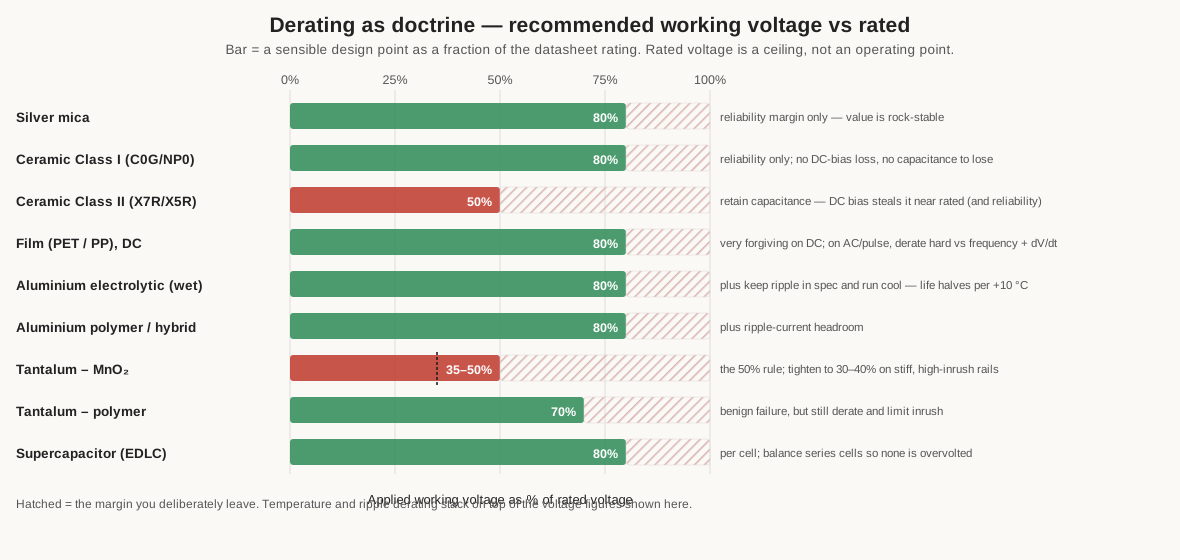
For Class II ceramic the derating is as much about keeping the capacitance as about reliability: because DC bias steals value near the rating, running at half the rated voltage (or picking a rating two to three times the working voltage) is what leaves usable capacitance on the rail. For tantalum the derating is a fire-safety statistic: the long-standing 50 % rule, tightened to 30–40 % on stiff, high-inrush rails, moves the part down the surge-failure curve, and it pairs with inrush limiting, as the tantalum volume detailed. For the wet aluminium electrolytic the voltage derating is gentler (around 80 %), but it is temperature and ripple that dominate its life — every 10 °C cooler roughly doubles the endurance, so keeping ripple in spec and mounting the part cool is worth more than voltage margin. Film is the most forgiving on DC and can run near its rating, but its AC rating is a separate, much lower number that falls with frequency, so an AC or pulse role derates the DC figure hard. Class I ceramic, silver mica, and the polymer parts want modest reliability margin but carry no bias-loss penalty. And a supercapacitor must not exceed its low per-cell voltage, with series stacks balanced so no cell is over-stressed. The universal move is the same in every case: leave headroom, and remember that the temperature and ripple derating stack on top of the voltage derating rather than instead of it.
12.6 Common mistakes
The failures that recur on the bench are, almost without exception, a parameter from the checklist that went unasked. A gallery of the classics, each traceable to an earlier volume:
- Using Y5V (or Z5U) where the value matters. A Class III ceramic can lose over 80 % of its capacitance across temperature before any bias is applied, and its cold limit rules out anything that leaves a heated room. Fine as a non-critical bulk bucket; disastrous as a filter, timing, or coupling cap. The third letter of the code is a character reference, and V means “do not rely on me.”
- Trusting a “10 µF” MLCC that is 3 µF under bias. The most common decoupling error: specifying a high-K ceramic by its marked value and getting a third of it on the live rail. Over-specify, move up a case size or voltage rating, or use a bias-flat family — but check the bias curve before finalising.
- An MnO₂ tantalum across a stiff rail with no inrush limit. Hot-plugging a discharged solid tantalum onto a charged low-impedance bus is the textbook way to ignite one. Derate hard, add series impedance or a soft-start, or — for new designs — use polymer tantalum, whose failure is a benign open.
- Under-rating ripple in an SMPS output cap. A capacitor that is “correct” in value and voltage but under-rated in ripple current overheats from the inside, its ESR climbs, the heating worsens, and it walks into thermal runaway and a vented can. In a switcher, ripple current and ESR are the ratings that matter; capacitance is almost incidental.
- Substituting a non-safety cap across the mains. An ordinary film or ceramic part in an X or Y position may fail short and defeat a safety barrier the equipment was certified to have. Only agency-marked X/Y parts belong there, and never an X part in a Y slot.
- Ignoring ESR in a switcher, or reaching for it in the wrong family. A general-purpose electrolytic dropped into a low-ESR position runs hot and unstable; conversely, an ultra-low-ESR ceramic bank on a linear regulator’s output can push it into oscillation. ESR is a design parameter to be matched, not merely minimised.
- A high-K ceramic in a precision filter or a low-distortion signal path. Its voltage coefficient turns the signal into distortion and its tempco moves the corner frequency. Reach for C0G or film; the capacitance density is not worth the errors it injects.
- Confusing the polarity conventions. The aluminium stripe marks minus; the tantalum bar marks plus. Wire a tantalum as if it followed the aluminium habit and it goes in reversed — quickly fatal for a tantalum, a vent for an aluminium.
Every one of these is a case of a real, published parameter being left off the checklist. None is exotic; all are avoidable by running the questions.
12.7 Pick a capacitor in 30 seconds
For the recurring questions, the framework compresses to a set of defaults. Figure 6 is the wallet card: the ten jobs that come up most, each mapped to a sensible starting part. They are defaults, not laws — the exceptions live in the family volumes — but they are the answers that rarely embarrass you.
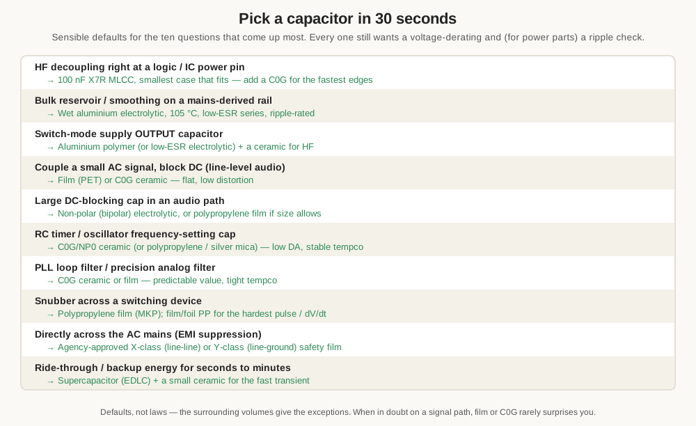
The defaults, in words: high-frequency decoupling at a chip pin, a 100 nF X7R MLCC in the smallest case that fits, plus a C0G for the fastest edges; a mains-derived reservoir, a 105 °C low-ESR wet aluminium electrolytic sized by ripple; a switch-mode output, aluminium polymer or a low-ESR electrolytic with a ceramic alongside; a small audio coupling cap, film or C0G; a large audio DC-block, a non-polar electrolytic; a timer or oscillator cap, C0G/NP0 (or polypropylene, or silver mica at RF); a PLL or precision filter, C0G or film; a snubber, polypropylene film; across the mains, an agency-approved X- or Y-class safety part; and seconds-to-minutes backup, a supercapacitor with a small ceramic for the transient. Memorise those ten and the great majority of everyday choices are made before the datasheet is opened.
12.8 The selection, in one paragraph
The families exist because the underlying trade — permittivity against stability, capacitance against loss, farads against honesty — has no single winner, so each construction optimises a different corner of it. Selection is the disciplined act of matching the corner the job lives in to the family that owns it: precision and low loss to the paraelectric ceramics, film, and mica; high-frequency impedance to the multilayer ceramic; cheap bulk farads to the aluminium electrolytic; dense, stable, low-profile bulk to the tantalums and polymers; punishing pulse and AC to polypropylene; safe mains connection to the agency-rated safety parts; and long-duration energy to the supercapacitor. The framework is always the same handful of questions — value and tolerance, voltage and derating, ripple and ESR, stability, polarity, size, temperature, lifetime, cost, and safety — asked in order and answered honestly. Ask them, and the part usually chooses itself. The rest of this deep dive is the evidence behind each answer: the physics in the real-capacitor volume, the constructions in the manufacturing volume, and the character of each family in its own. This volume is only the index that points, for a given job, at the right one.
Comments (0)